Tecfluid SC-250 User Manual
Page 9
9
MECHANICAL MAINTENANCE
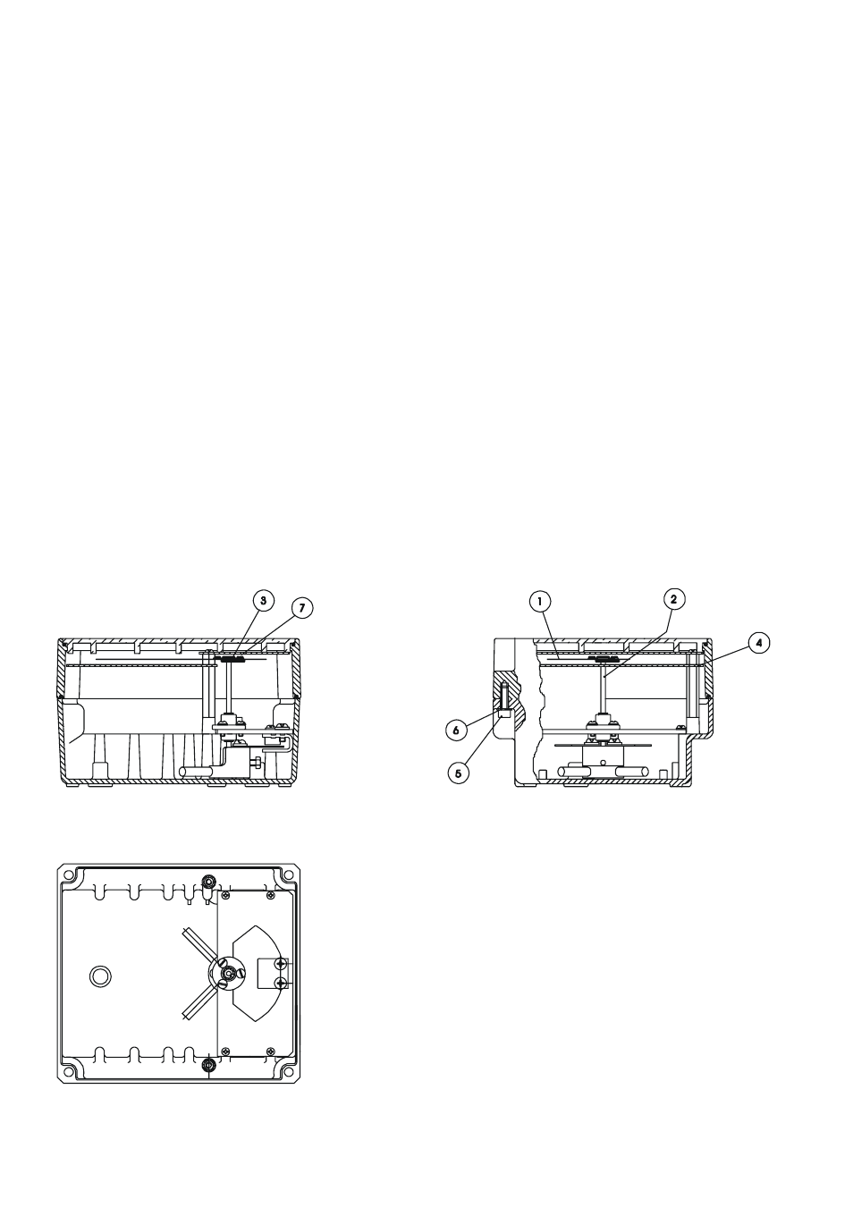
Indicating housing
If operating anomalies are detected with the meter, the following points should be checked. If
necessary disassemble the front cover which is held by four M5 Allen screws (5) and plastic
washers (6) for the hermetic seal, at the back of the indicating housing.
1. THE INDICATOR NEEDLE (1) RUBS ON THE READING SCALE (4).
This normally happens if the meter has been hit or dropped. Simply straighten it out by bending it
slightly until it is separated by between 2-3 mm from the reading scale surface (4)
2. THE INDICATOR NEEDLE (1) DOESN’T READ 0 ON THE SCALE.
For this, the meter should be placed in its real working position on top of a NON-MAGNETIC
table. If when the float is moved the needle moves but does not return to 0, check that the needle
hub (3)
is firmly attached to the pointer shaft (2). If it isn’t, secure the needle hub (3) onto the
conical tip (2) of the shaft by tapping it lightly and carefully.
This may have happened during haulage or through the meter being dropped, make the indicator
needle coincide with 0 using the frontal adjusting screw (7) on the indicator needle, screw to left or
right wherever convenient. Make sure that the shaft (2) is held fast so as not to be bent or
damaged
Check that there is no rubbing between the needle movement system and limit switch or
transmitter connecting cables .
This way the flow meter will be properly adjusted to give correct readings.