Tecfluid SC-250 User Manual
Page 7
7
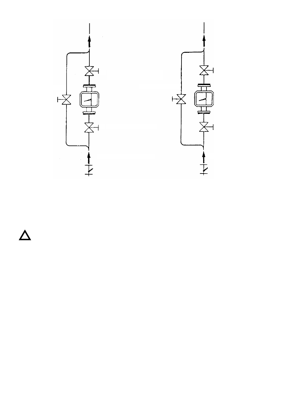
VALVULA BY-PASS
3
2. VALVULA DE REGULACION
1. VALVULA DE CIERRE
2. VALVULA DE
CIERRE
VALVULA BY-PASS
3
1. VALVULA DE
REGULACION
INSTALACION PARA GASES
INSTALACION PARA
LIQUIDOS
Figura 3
Figura 4
OPERATION
Once the meter is installed, the regulator valve should be opened slowly. The fluid flow will move
the float which, through magnetic coupling, moves the indicating needle.
Any variations of working conditions with respect to those when calibrated can induce
reading errors. The calibration working conditions are indicated on the instrument’s face
plate.
GAS MEASUREMENT. (Figure 3)
THE WORKING PRESSURE IS OF MAXIMUM IMPORTANCE for correct GAS measurement as
it directly affects the scale readings.
Therefore if a meter is calibrated for 2 bar and it’s working at 1 bar there will be an error of 22%.
In order for the meter to work at the calibration pressure (nominal working pressure) and to obtain
a back pressure that will maintain the float equilibrium, the regulating valve should be mounted as
shown in Figure 3.
The flow should be controlled by the meter outlet valve, while keeping the inlet one fully open. The
by-pass valve should be fully shut off.
If the regulation is done using the inlet valve, in open circuits or at low gas flow in the meter, the
gas will expand which will sharply diminish its density, giving very serious reading errors.
If the flow is regulated by the inlet valve, the float usually experiences an oscillating movement
which produces a shut off action until sufficient pressure is gained to overcome its weight. The
sudden fall of pressure, when the gas escapes, will make it fall. This cycle is repeated until the
valve is closed or is sharply and fully opened and then closing the valve until it takes it back to the
desired flow rate.
This does not mean that this phenomenon will not occur again if the flow is continued to be
regulated by the inlet valve.
!
BY-PASS VALVE
3
2. REGULATOR VALVE
1. SHUT OFF VALVE
2. SHUT OFF
VALVE
BY-PASS VALVE
3
1. REGULATOR
VALVE
INSTALLATION FOR GASES
INSTALLATION
FOR LIQUIDS
Figure 3
Figure 4