1 facilities connecting conductive parts to earth, 2 maintenance, 3 technical data for the atex version – Tecfluid TM Series User Manual
Page 15
15
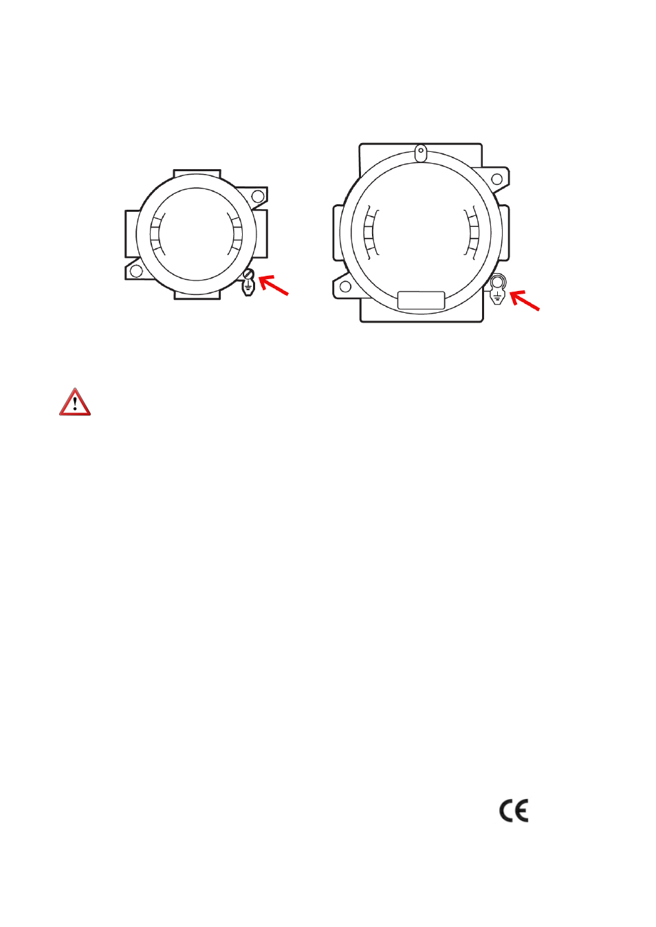
9.2.1 Facilities connecting conductive parts to earth
When the instrument is not grounded securely through the connection process, it should
be grounded through the housing screw, as shown in the figure.
9.2.2 Maintenance
NOTE: When the flameproof enclosure contains an electronics model CIP or CIP II, it
should never be opened in presence of explosive atmosphere.
For the rest of models, before any maintenance that involves opening the flameproof
enclosure, make sure there is no voltage in any of internal components.
The is no special maintenance for the ATEX version.
9.2.3 Technical data for the ATEX version
Temperature
Ambient temperature: -20 ... +60 ºC
Electrical connection
Inside the flameproof enclosure.
Recommended cable
The standard thread supplied for the cable gland connection is 3/4” NPT.
ATEX cable glands for non-armoured or armoured cables can be placed .
The outer diameter of the cables that fits the 3/4” NPT cable glands is between 6 and 21
mm.
Associated electronics
CIP / CIP II: Battery powered volumetric counter.
CP ... CH420: 2-wire analog transmitter with flow rate and volume indication.
HART protocol optional.
Conforms to 94/9/EC Directive (equipment and protective systems intended for use in
potentially explosive atmospheres).
The rest of characteristics are the same as in the point 6.