7 electrical connection – Tecfluid TM Series User Manual
Page 7
7
3.7 Electrical
connection
It is important to keep the connecting cable between the flowmeter and the auxiliary
electronics away from mains or power supply cables, in order to avoid interferences. In
any case, those should be separated at least 5 cm.
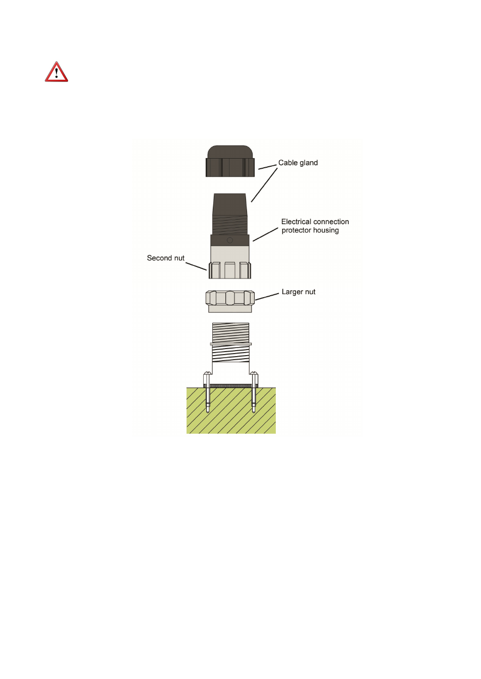
The turbine flowmeter has an IP65 connector fastened to the counter by means of 4
screws. The connector consists of 3 parts joined by threaded nuts. (See figure).
Loosening the larger nut in the middle of the connector allows us to withdraw the half
where the cable will be later soldered.
The other half of the connector is fixed to the counter and should not be removed, except
when servicing the detector (See point 4.5 of the MAINTENANCE section).
The removable part of the connector consists of the cable gland at the top and the
electrical connection protector housing.
Before starting the installation, check that the cable gland is the right size for the cable to
be used. This will guarantee the instrument will stay watertight. The cable gland used is
for cables with outside diameters between 6 mm and 10 mm.
The electrical connection protector housing is dismounted by loosening the second nut.
When this is removed, the three connector terminals are visible.