TS Performance 5130100 User Manual
Page 6
Continued
Dodge 6.7L
1. Locate the Crank Position Sensor on the front of the engine. It can be accessed from under the truck.
Route the White wire from our wire harness to the Crank Sensor. Using the supplied T-tap connects
the white wire to the Outside wire towards front of truck on the Crank Sensor connector.
2. Locate the Fuel Pressure Sensor on the driver’s side of the engine. IT is the connector on the back of
the fuel rail with the three pin connector. Route the Purple wire to the Fuel Sensor and using the
supplied T-tap, connect it to the middle wire in the connector.
3. Locate the MAP Sensor on the intake air plenum on the driver’s side of the engine. The MAP sensor
is located on the back side of this plenum and will have a three pin connector. T-Tap the brown wire
farthest to the driver’s side of the connector.
Duramax LB7, LLY, LBZ
1. Locate the Engine Harness Connector on the driver’s side of the
engine. This will be the larger of the two connectors. Route the
white wire from our wire harness to the connector. Use the
supplied T-tap to connect it to the blue wire with a white tracer.
It will be identified as B9 in the connector. The wires are
labeled A-D from the bottom to the top and 1-12 from the front
of the truck to the rear.
2. Locate the Fuel Pressure signal wire in the Engine Harness
Connector. Route the Purple wire to the Engine Harness
Connector. Connect it to the Yellow wire in location C5. The
wires are labeled like explained in step 6.
3. Locate the MAP Sensor signal wire in the Small Engine Harness Connector. This is located just above
the lager Engine Harness. Route the Blue wire to the harness and connect it to the Light Green wire in
location C8. The wires are labeled A-C from the bottom to the top and 1-12 from the front to the rear.
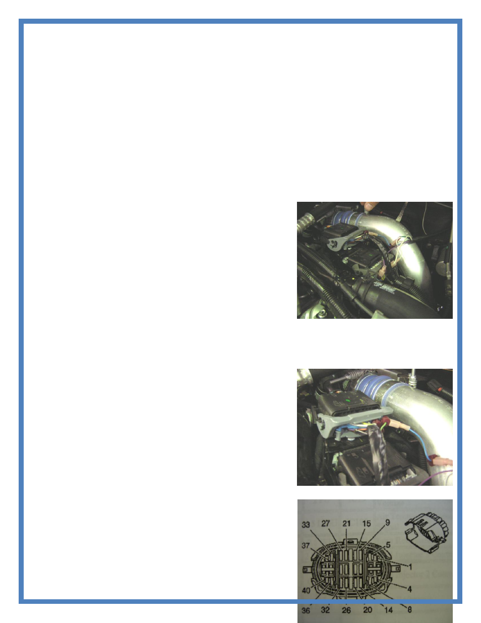
Duramax LMM
1. Locate the Fuel Rail Pressure Sensor in the lower Black Engine
Harness Connector. Using the Harness diagram supplied the
Fuel Rail Pressure., it is a yellow wire, located in Pin 23.
Connect the Purple wire from our harness to this pin using the T-
tap Connector
2. Locate the MAP Sensor Connector in the same harness. It is a
light green wire, located in Pin 18 Connect the Blue wire from
our harness using the T-tap connector.
3. Locate the Tack wire in the same engine harness . It is a white
wire with a black tracer, located in Pin 17. Connect the White
wire from our harness using the T-tap connector.
If there are any questions on the product or installation of the module
give us a call at TS Performance (270) 746-9999
Figure 9: Main Harness Connectors