Verilink DCSU 2911 (880-502647-001) Product Manual User Manual
Page 48
DCSU 2911 E1 Craft Interface
4-2
Verilink DCSU 2911 User Manual
In the screen displayed
•
Slots containing DCSU modules display a U at the intersection
of rows and columns designating the shelf/slot location of the
DCSU module.
•
The letter surrounded by brackets (
[ ]
) indicates the location
of the module that is referenced and modified via submenus
of the ACE Controller Menu (Main Menu).
•
On initial log in, brackets surround the module being used as
the log-in access point.
•
The option S (shelf/slot) is used to move to a desired module
in the node.
In Figure 2-1, the Main Menu shows a DCSU 2911 (designated by U)
in slot 1. The currently accessed module is indicated by the square
brackets ([ ]). The asterisk next to the U indicates the DCSU 2911
that is the node master.
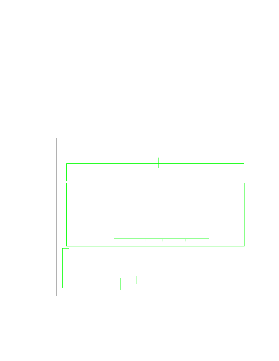
Figure 4-1 ACE Controller Menu
The Main Menu displays the following:
1. In the menu heading area, the location of the DCSU Controller
(by shelf and slot,
[1,1]
) and the firmware revision (
FW Rev
).
-- VERILINK ACE CONTROLLER at [1,1]: FW Rev 1.44, Dec 11 1996 --
Site Name:
Access level: 4
<- SLOT ->
SHELF 1 2 3 4 5 6 7 8 9 10 11 12 13
0 - - - - - - - - - - - - -
1 D [*U] -
2 - - - - - - - - - - - - -
3 - - - - - - - - - - - - -
4 - - - - - - - - - - - - -
5 - - - - - - - - - - - - -
6 - - - - - - - - - - - - -
7 - - - - - - - - - - - - -
KEY: *=CONTROLLER N=NCM Q=QUAD M=IMUX A=DIDCSU P=DPRI U=DCSU
S) shelf/slot O) node administration
C) configuration D) diagnostics
P) performance/status A) alarm
B) circuit I) manufacturing info
X) system log off
[1,1] DCSU 2911 >
Menu Heading Area
Node “map
(Physical Location
Command
D a ta E n try P ro m p t
List
of Modules)
Screen Key Letters