Shdsl interface pin assignments, G.703 connector pin assignments, Supervisory port pin assignments – Verilink WANsuite 5650 (34-00314.E) Product Manual User Manual
Page 68
A-8
W A N s u i t e 5 6 5 0
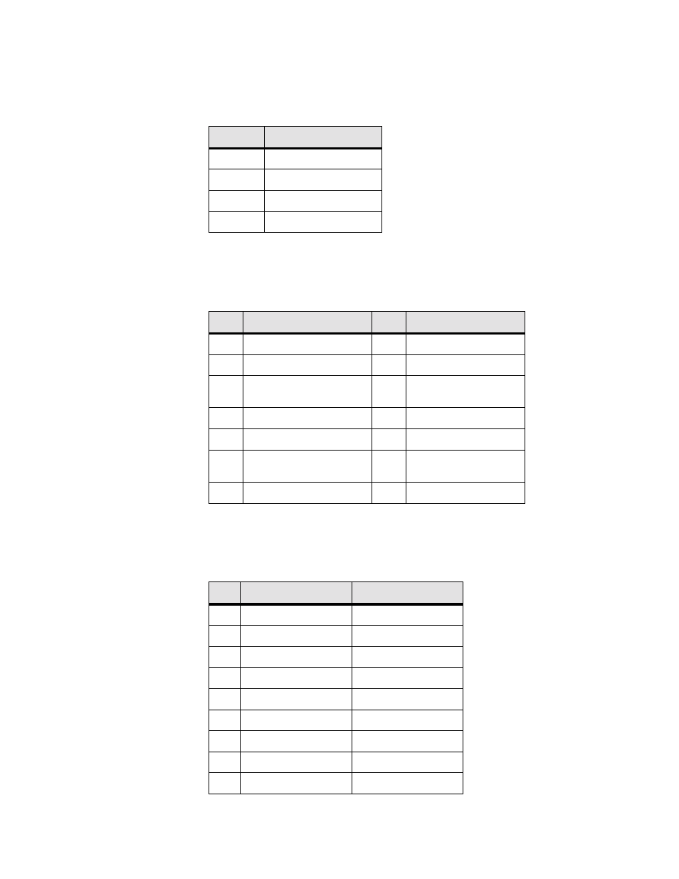
SHDSL Interface Pin Assignments
The
SHDSL
interface is a standard eight-pin modular jack. The table below
displays the pinout assignments.
G.703 Connector Pin Assignments
The
G.703
physical interface is a standard eight-pin modular jack. The table
below displays the pinout assignments.
Supervisory Port Pin Assignments
The
SUPERVISORY PORT
interface is a standard DB-9, nine-pin modular
jack. The table below displays the pinout assignments.
Pin
DSL NET Interface
1, 2, 3
Not used
4
ANALOG Input/Output
5
ANALOG Input/Output
6, 7, 8
Not Used
Pin
E1 Equipment Interface Pin
Signal
1
Data Out
1
Data In
2
Data Out
2
Data In
3
Internally strapable to
Chassis return
3
Internally strapable to
Chassis return
4
Data In
4
Data Out
5
Data In
5
Data Out
6
Internally strapable to
Chassis return
6
Internally strapable to
Chassis return
7, 8
Not Used
7,8
Not Used
Pin
DCE Mode
DTE Mode
1
DCD out
LL out
2
Rx Data out
Tx Data out
3
Tx Data in
Rx Data in
4
DTR in
DSR in
5
Signal Ground
Signal Ground
6
DSR out
DTR out
7
RTS in
CTS in
8
CTS out
RTS out
9
No connect
No connect