Align sensor to roadway, Determine the height and mount the sensor – Wavetronix SmartSensor Matrix (SS-225) - Quick-reference Guide (Installer) User Manual
Page 2
4
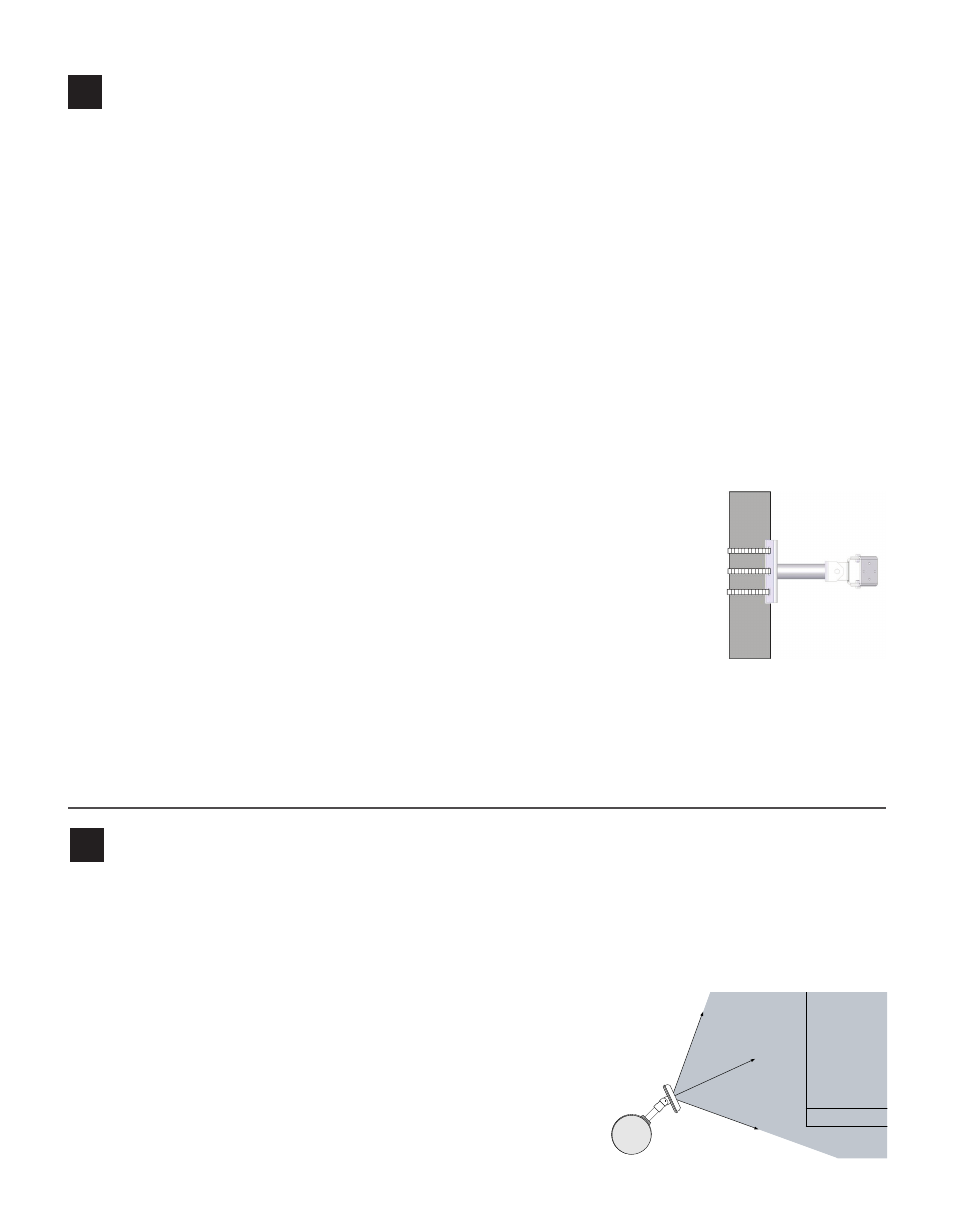
Align sensor to roadway
3
Determine the height and mount the sensor
Use the following guidelines to determine the best mounting height:
˽
The sensor should be placed at a height of roughly 20 ft., give or take 5 ft. (6.1 ± 1.5 m).
˽
The maximum recommended mounting height is 60 ft. (18.2 m). The minimum recommended mount-
ing height is 12 ft. (3.6 m). (The farther you install the sensor from the first lane of interest, the higher
the sensor should be mounted.)
˽
Take into consideration the sensor’s footprint, which reaches 140 ft. (42.7 m) from the sensor. Place the
sensor so that the footprint covers all the areas of interest. Be aware that in certain conditions, lanes that
have stop bars or detection zones placed at extended range may show some loss in performance, even
with a proper mounting height.
˽
The mast arm is frequently a good place to mount the sensor.
˽
The mounting position should have a clear view of the detection area. Poles, mast arms, signal heads or
other objects should not block the view of the detection area.
˽
Placing the sensor higher will result in less occlusion. Placing it lower could result in more occlusion.
However, if the nearest detection area is less than about 20 ft. (6.1 m) away, the sensor may perform bet-
ter with a lower mounting position.
To attach the mount bracket to the pole:
1 Insert the stainless steel straps through the slots in the mount bracket.
2 Position the mount on the pole so the mount head points toward the lanes of
interest at a 45° angle.
3 Tighten the strap screws.
To securely fasten the sensor to the mount bracket:
1 Align the bolts on the sensor’s backplate with the holes in the mount bracket. The eight-pin connector
receptacle on the bottom of the sensor should be pointing towards the ground.
2 Place the lock washers onto the bolts after the bolts are in the mount bracket holes.
3 Thread on the nuts and tighten.
The sensor’s field of view fans out 45° to both sides. You will usually want to position the radar beam so that
its 90° footprint covers all lanes approaching the stop bar.
Also, the field of view’s front edge must be aligned to provide some coverage beyond the stop bar so you can
detect vehicles that don’t stop at or behind the stop line, as well as vehicles exiting queues.
1 Adjust the side-to-side angle so the front edge of the field of view
provides a view downstream of the stop bar.
2 Tilt the sensor down to aim it at the center of the lanes of interest.
3 If necessary, rotate the sensor so that the bottom edge of the
sensor is parallel with the roadway. This is necessary where the
intersection approach has a significant grade.
45°
45°
Edge of First Lane of Interest
Pan sensor towards
stop bar
Stop Bar