Wire power to backplate, Attach the 6-conductor cable and ground the sensor – Wavetronix SmartSensor Matrix (SS-225) - Quick-reference Guide (Installer) User Manual
Page 3
7
Wire power to backplate
5
Attach the 6-conductor cable and ground the sensor
1 Tear the tab off the silicon dielectric compound and squeeze about 25% of it into the connector at the
base of the sensor. Wipe off any excess compound.
2 Insert the cable into the connector and twist clockwise until you hear it click into place.
3 To avoid undue movement from wind, strap the cable to the pole or run it through a conduit, but leave
a small amount of slack at the top of the cable to reduce strain.
The SmartSensor Matrix provides its own surge protection, so there is
no need for a pole-mount box on the sensor side of the cable. Instead,
the cable should run straight to the main traffic cabinet; landing the
cable in the cabinet will be covered later in this document.
It is necessary, however, to ground the sensor:
1 Connect a grounding wire to the grounding lug on the bottom of
the sensor.
2 Connect the other end of the grounding wire to the earth ground for the pole that the sensor is
mounted on. Do not attempt to run the grounding wire back to the main traffic cabinet.
6
Mount the preassembled backplate in the main traffic cabinet
The SmartSensor Matrix preassembled backplate must be installed in the main traffic cabinet. To do so,
locate the area planned for mounting the backplate; it can usually be mounted on the side panel of a NEMA-
style cabinet. Then attach the backplate with the U-channel mounting screws.
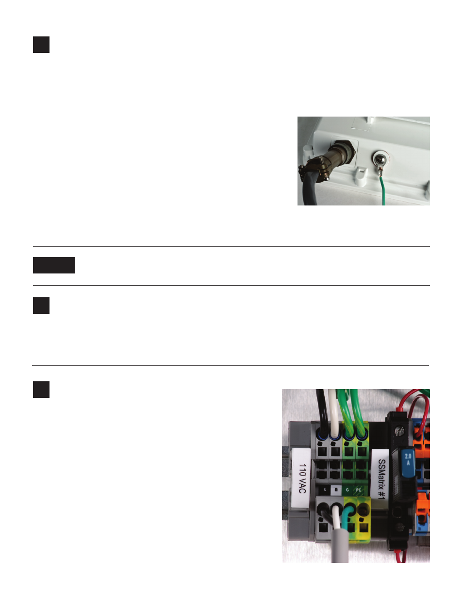
Use the following steps to connect power to the AC terminal
block on the bottom DIN rail:
1 Connect a line wire (usually a black wire) to the bottom of
the “L” terminal block.
2 Connect a neutral wire (usually a white wire) to the bottom
side of the “N” terminal block.
3 Connect a ground wire (usually a green wire) to the bottom
of the “G” terminal block.
4 Turn on AC mains power.
5 Press the circuit breaker switch on the left side of the top
DIN rail to switch power to the backplate.
6 Verify power is regulated by seeing that the DC OK LEDs
are illuminated on the Click 201/202/204.
If you’re using a Click 650 with your Matrix, consult the 650 quick reference guide for the rest
of your installation. If you’re using a preassembled backplate, complete the steps below.
Note