Terminate the smartsensor 6-conductor cable, Connect to the detector rack cards – Wavetronix SmartSensor Matrix (SS-225) - Quick-reference Guide (Installer) User Manual
Page 4
WX-500-0172
© 2015 Wavetronix LLC. All rights reserved. Protected by US Pat. Nos. 6,556,916; 6,693,557; 7,426,450; 7,427,930; 7,573,400; 7,889,097; 7,889,098; 7,924,170; 7,991,542; 8,248,272; 8,665,113;
and Cdn. Pat. Nos. 2,461,411; 2,434,756; 2,512,689; and Euro. Pat. Nos. 1435036; 1438702; 1611458. Other US and international patents pending. Wavetronix, SmartSensor, Click, Com-
mand and all associated logos are trademarks of Wavetronix LLC. All other product or brand names as they appear are trademarks or registered trademarks of their respective holders.
Product specifications are subject to change without notice. This material is provided for informational purposes only; Wavetronix assumes no liability related to its use.
8
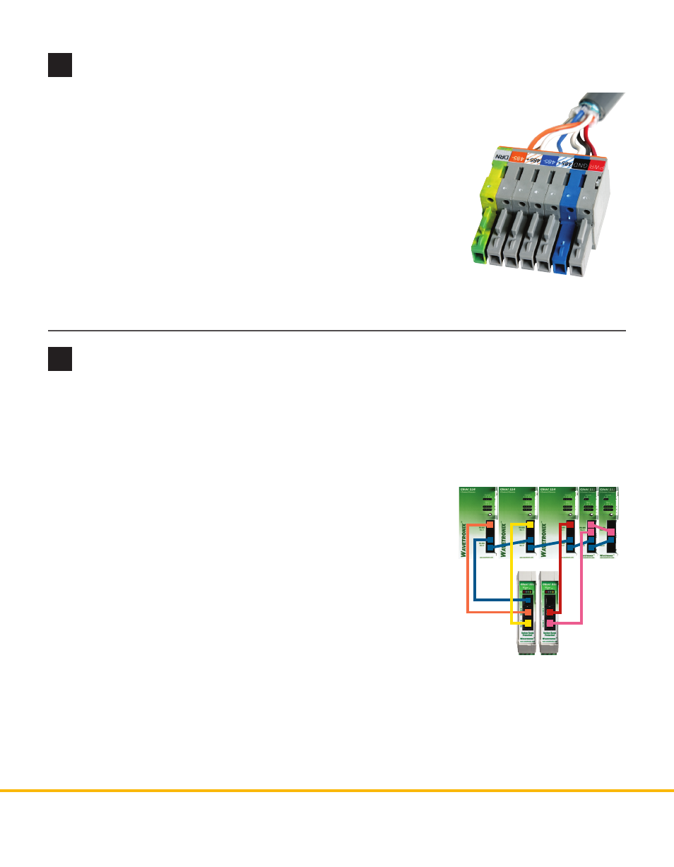
Terminate the SmartSensor 6-conductor cable
9
Connect to the detector rack cards
Finally, connect to detector rack cards. You can use the Click 104, which mounts on a DIN rail, but these
instructions refer specifically to the Click 112/114 detector rack cards.
The Click 222 has three RJ-11 jacks on the faceplate; these jacks have the following functions:
˽
RS-485 A – Connects the data bus from sensor 1 to the detector rack cards.
˽
RS-485 B – Connects the data bus from sensor 2 to the detector rack cards.
˽
RS-485 Bridge – Connects the configuration buses from sensors 1 and
2 to the control bridge, to the detector rack cards, and to the T-bus.
This jack combines the input from ports C and D.
Note. For information about how to configure the Click 112/114, see the
Click 100-400 Series User Guide or the Click 112/114 Quick-Reference Guide.
To connect to the detector rack cards:
1 Make sure the DIP switches are set.
2 Connect from the Click 222 RS-485 A port to a bus 1 port on the ap-
propriate rack card. Connect from the Click 222 RS-485 B port to a bus
1 port on another rack card.
3 If you are using Click 112 cards, use a patch cord to share bus 1 between cards dedicated to the same
sensor. If you have more than two sensors in your system, repeat steps 1–3 to connect bus 1 for all
remaining rack cards.
4 Connect from a Click 222 bridge port to bus 2 of the rack cards.
5 Daisy-chain between the bus 2 ports of all of the rack cards for device configuration.
To land the 6-conductor cable into the terminal block section:
1 After routing your SmartSensor 6-conductor cable into the cabinet, carefully strip
back the cable jacket and shielding on the service end of the cable.
2 Open the insulation displacement connectors on the plug by inserting a
small screwdriver into each square slot and rocking it back.
3 Insert the wire leads into the bottom side of the plug-in terminal accord-
ing to the colors of the wires and the labels on the plug. Make sure the
wires are completely inserted in the terminal.
4 Close the insulation displacement connector by reinserting the screw-
driver into the square slot and rocking it forward. The plug-in terminals
will automatically complete the electrical connection. There is no need
to manually strip the insulation on the end of each wire.
5 If you removed the plug to wire it, insert it back into the terminal block section.