Wavetronix Click 500 (programmable controller) (CLK-500) - User Guide User Manual
Page 77
76
CHAPTER 8 • CLICK 511
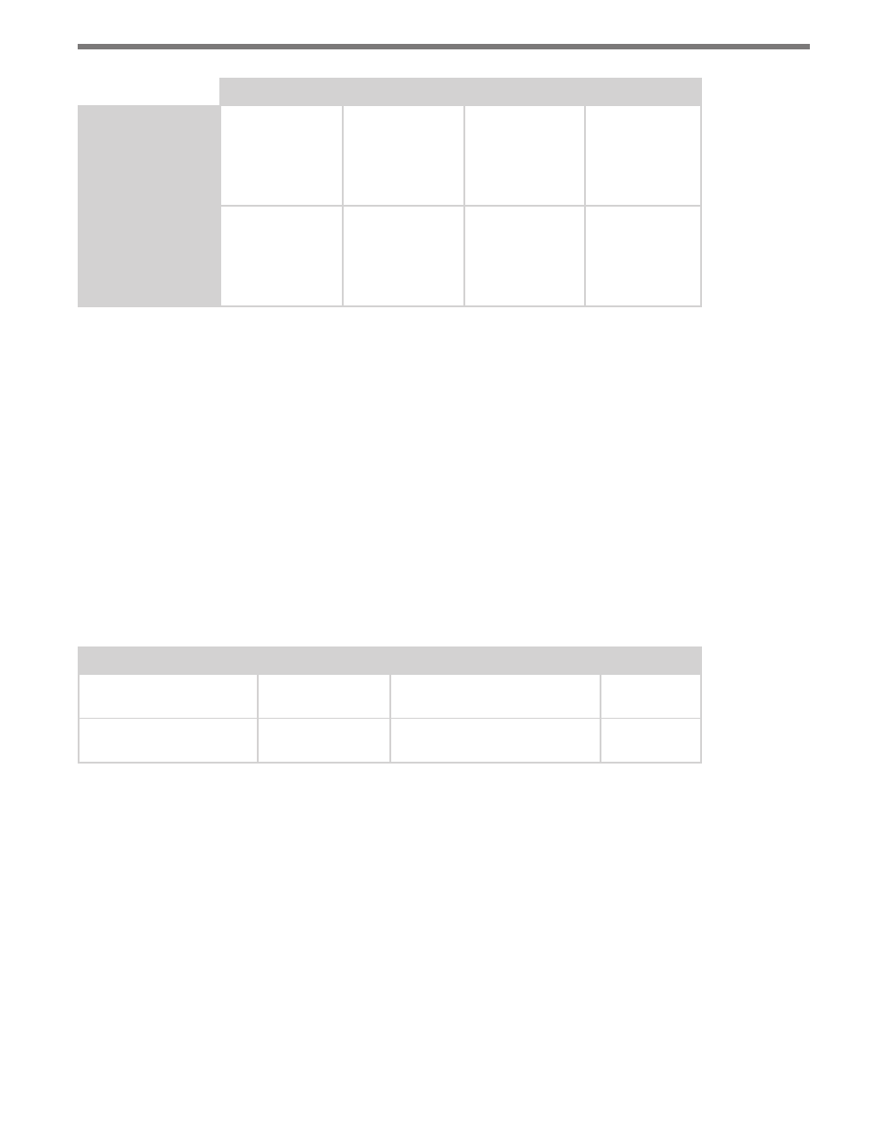
1st LED
2nd LED
3rd LED
4th LED
Submenu 1 (Yel-
low LEDs)
Solid –
Poll count 1
Flashing –
Poll count 5
Solid –
Poll count 2
Flashing –
Poll count 6
Solid –
Poll count 3
Flashing –
Poll count 7
Solid –
Poll count 4
Flashing –
Poll count 8
Submenu 2 (Red
LEDs)
Solid –
Timeout = 1 sec
Flashing –
Timeout = 5 sec
Solid –
Timeout = 2 sec
Flashing –
Timeout = 6 sec
Solid –
Timeout = 3 sec
Flashing –
Timeout = 7 sec
Solid –
Timeout = 4 sec
Flashing –
Timeout = 8 sec
Table 8.3 – Server Mode Submenus (Yellow and Red LEDs)
By default, input 1 of client device IDs 1–8 are scheduled to be queried if the poll count is
specified to be 8. If you wish to alter the poll sequence, you can send serial messages via a se-
rial terminal program. The first message is sent to specify the sequence of client device IDs
to query. Another message is sent to specify the sequence of inputs to query. For example,
if you would like query both digital inputs of the first four client device IDs you could send
the following commands:
“ZW0000S111223344\r”
“ZW0000S212121212\r”
The “\r” indicates a carriage return. If the command is received by the server module it will
respond with an “OK” message. The format of these messages is shown in Table 8.4.
Command
Header
Payload
Footer
Device ID Poll List
Request Command
“ZW0000S1”
Eight bytes specifying the
order of device IDs
“\r”
Input Number Poll List
Request Command
“ZW0000S2”
Eight bytes specifying the
order of device inputs
“\r”
Table 8.4 – Poll List Command Format
Once the mode begins operating, the yellow LEDs will light up to indicate which slot in the
polling list is currently being queried. So if the poll count is 8 you will see the yellow LEDs
1–4 light up solid, after which they will light up flashing.
As each device in the poll list is queried, the status will be signaled using the red LEDs. If
the red LED below the active yellow LED lights up solid then the associated digital input is
ON. If the red LED below the active yellow LED flashes then the associated digital input is
OFF. If the red LED below the yellow LED is blank, then the response timed out. If red LED
1 and 4 light up, then the response has timed out 10 or more times consecutively.