Westermo ODW-720-F1 User Manual
Page 13
13
6651-2221
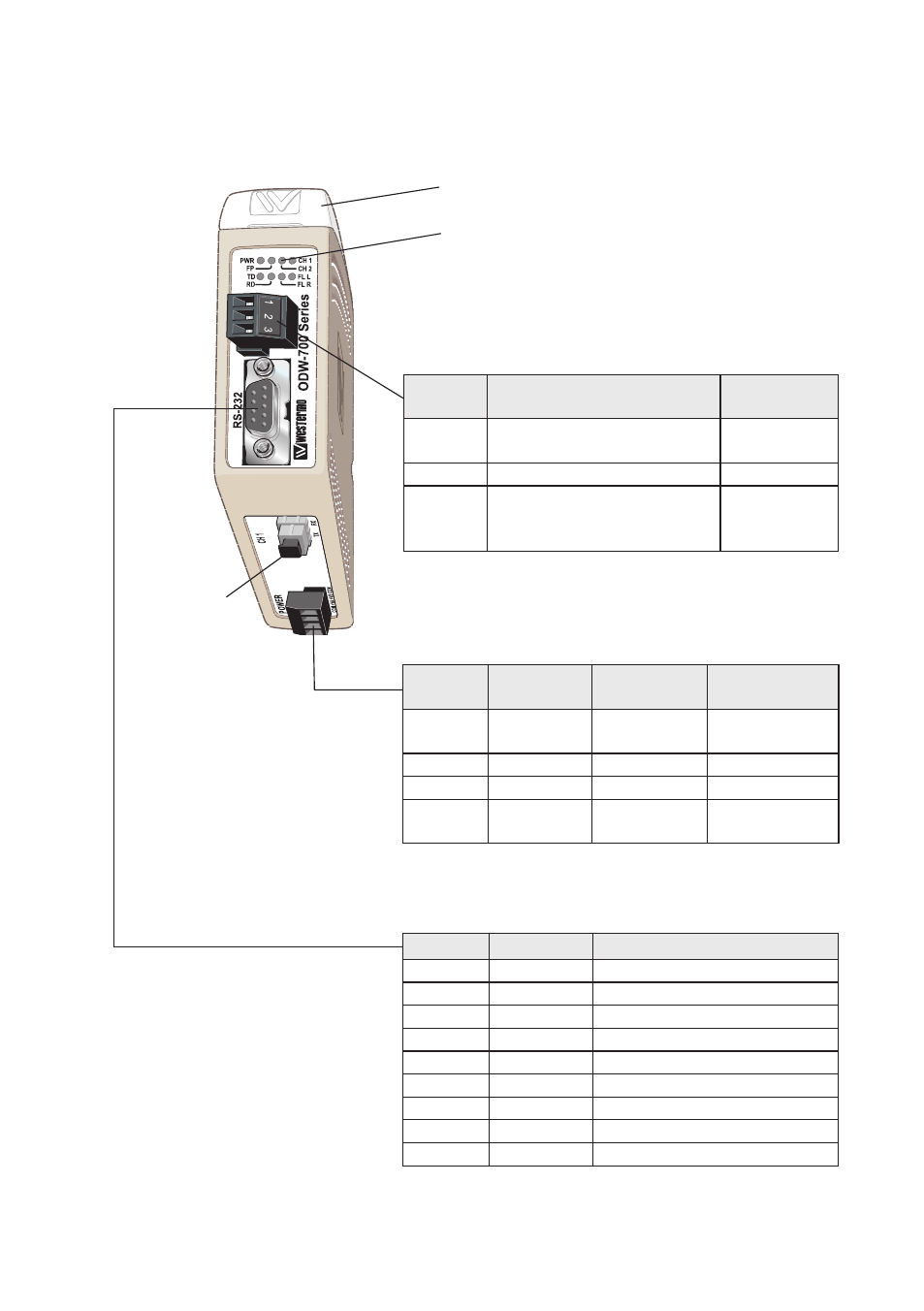
Location of Interface ports, LED’s and DIP-switches
ODW-720-F1
LED Indicators
(for details see page 15)
DIP-switches accessible under lid
(for details see page 16)
FX(Fibre)
(for details
see page 12–13)
* Direction relative this unit
Status
screw terminal
Position Description
Product
marking
1
Contact with C when fibre
optical links are in operation
NO
2
Common
C
3
Open (no contact with C)
when fibre optical links are
not in operation
NC
Position Direction* Description
Product
marking
1
In
Common
voltage
COM
2
In
Voltage A
+VA
3
In
Voltage B
+VB
4
In
Common
voltage
COM
Power
screw terminal
Position Direction* Description
1
Out
Data Carrier Detect (DCD)
2
Out
Received Data (RD)
3
In
Transmitted Data (TD)
4
Not connected
5
–
Signal Ground (SG)
6
Out
Data Set Ready (DSR)
7
In
Request To Send (RTS)
8
Out
Clear To Send (CTS)
9
Not connected
RS-232
D-sub