Switch settings, Connections, Td-300 dc – Westermo TF-300 User Manual
Page 9
Advertising
9
6606-2201
O
1
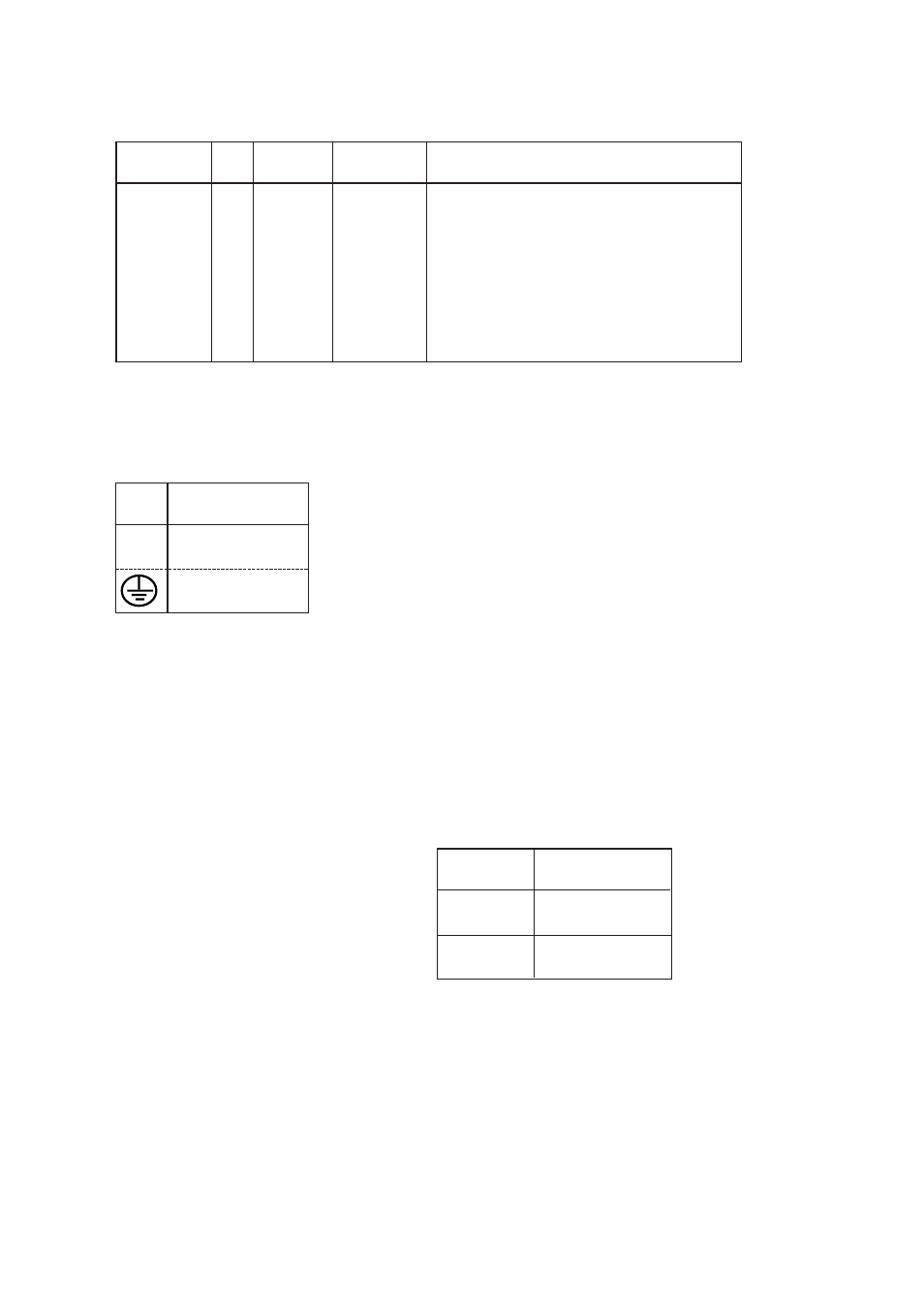
109
DCD/Data Carrier Detect
O
2
4
104
RD/Received Data
I
3
3
103
TD/Transmitted Data
NC
4
–
5
5
102
SG/Signal Ground
O
6
107
DSR/Data Set Ready
I
7
1
105
RTS/Request to Send
O
8
2
106
CTS/Clear to Send
NC
9
Signal description
Terminal connection (DTE)
(RS-232-C/V.24, 9-pole D-sub, female alt. 9-pole screw terminal)
Direction
Pin
no.
Screw-
terminal
CCITT V.24
Description
N
115V*/230V
L
AC power
PE/Protective Earth
Power connection (AC)
(3-pole screw terminal)
*) TD-300 115V
No.
Power
supply
1
– Voltage
2
+ Voltage
Connection
no.
Power
supply
Switch settings
According to TD-300 AC
Connections
According to TD-300 AC, except power supply
TD-300 DC
I = input O = output NC = not connected
Advertising