Running the cables, Hole drilling, Installing the remote switch – Airmar Switchboxes—SB264, SB260 User Manual
Page 2: Preparing the cables
Running the Cables
If new equipment is being installed, route the transducer cable(s),
the echosounder cable(s), the power cable, and the remote switch
cable to the proposed location of the switchbox before beginning
the installation.
• To reduce electrical interference from other electrical wiring
and any on-board equipment with strong magnetic fields such
as radar equipment, radio transmitters, boat engines,
generators, etc., separate the cables by at least 1m (3').
• Use grommets when passing cables through bulkheads and
other parts of the boat to prevent chafing.
• Use deck glands where necessary to prevent water seepage
into the boat.
• Allow an extra 25 cm (10") of cable for wiring ease.
• Do not fasten the cables in place at this time.
Hole Drilling
1. Remove the switchbox cover and set aside along with the four
screws. Hold the switchbox at the selected location and mark the
position of the screw holes.
NOTE: If the switchbox will be mounted on a vertical surface,
face the compression fittings downward to avoid any possibility
of water seeping into the box.
2. At the marked locations, drill 3mm or 1/8" holes to a depth of
10mm (3/8"). Do not fasten the switchbox in place at this time.
3. At the planned location for the switch, use the label as a
template to mark the hole (see Figure 1).
4. Drill a 3mm or 1/8" pilot hole. Using a 11mm or 1/2" drill bit, drill
the hole for the switch.
5. Sand the area around the hole, inside and out. Clean the
surface with a weak solvent such as alcohol to ensure the label
will adhere properly.
6. Apply the switch label by removing the backing from the
adhesive and pressing the label firmly into place.
Installing the Remote Switch
IMPORTANT: It may be easier to wire the remote switch before
installing it in the mounting surface.
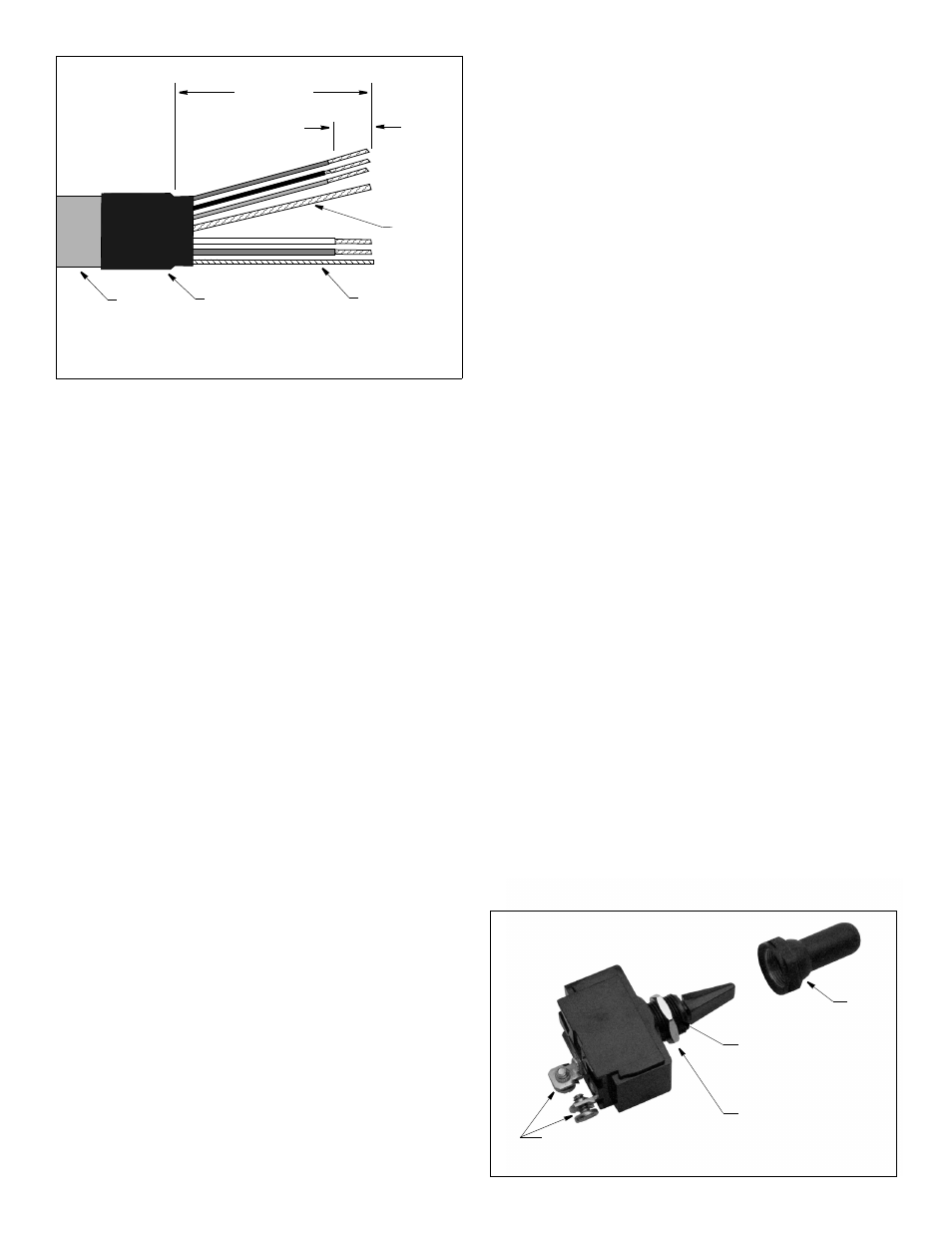
1. Strip 60mm (2-1/2") of the cable jacket and foil shielding from
one end of the C2 cable (see Figure 2).
2. Strip 10mm (3/8") of conductor insulation from the end of each
insulated wire in each cable.
3. Protect the cable’s foil shielding from causing a short by using
heat shrink tubing around the jacket where the wires emerge
from the cable. The tubing must overlap the wires a minimum of
6mm (1/4").
4. On the switch, unscrew the plastic ring and discard. It will not be
used. Unscrew the hexagonal nut and set aside.
5. Connect the blue wire to one of the screw terminals on the back
of the remote switch and the black wire to the other terminal
(see Figure 3). Either wire can be connected to either screw
terminal. It will not affect the performance of the switch.
Connect each wire by loosening a screw. Wrap the striped end
of the wire around the threads of the screw and tighten it again.
6. From the backside of the mounting surface, push the toggle
through the mounting hole. With the notch on the threaded stem
facing the word “Wide-Beam” or “A” on the label, screw the nut
against the surface. Tighten it with an adjustable wrench.
7. Screw the water-resistant boot onto the toggle switch.
Preparing the Cables
1. Allowing an extra 25 cm (10") for wiring ease, cut each cable to
length. Do not fasten the cables in place at this time.
2. Push approximately 200mm (8") of each cable through the
appropriate compression fitting. Follow the diagram on the
switchbox cover (see Figure 1). Be careful not to damage the
circuit board.
3. Strip 60mm (2-1/2") of the cable jacket and foil shielding from
the cut end of each cable (see Figure 2).
4. Strip 10mm (3/8") of conductor insulation from the end of each
colored wire in each cable.
5. Protect each cable’s foil shielding from causing a short inside
the switchbox by using heat shrink tubing around the jacket
where the wires emerge from the cable. The tubing must
overlap the wires a minimum of 6mm (1/4").
2
Figure 3. Installing the switch
Figure 2. Preparing the cable
(SS264W cable shown)
64mm (2 1/2")
remove cable jacket and
10mm
(3/8")
cable
jacket
inner bare
(depth)
outer bare
(shield)
remove
insulation
foil shielding
heat-shrink
tubing
Copyright © 2008 Airmar Technology Corp.
Copyright © 2008 Airmar Technology Corp.
hexagonal nut
boot
screw terminals
notch
faces word
“widebeam”
or “A” on label