Connecting the switchbox – Airmar Switchboxes—SB264, SB260 User Manual
Page 3
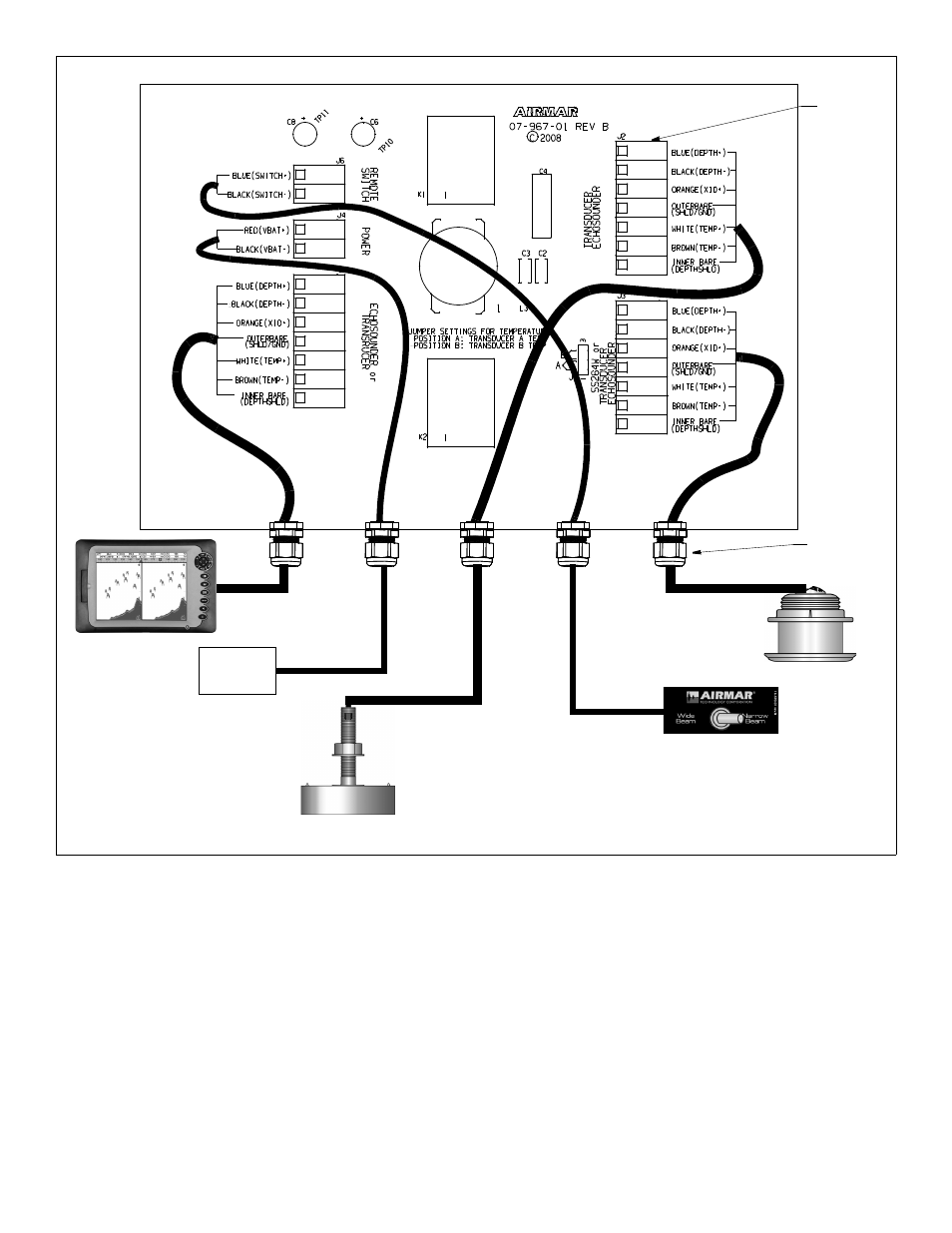
Connecting the Switchbox
CAUTION: Be sure to connect each wire to the correct terminal in
the correct terminal block.
Wire each cable to its corresponding terminal block (see Figure 4).
Follow the color code on the PC board. Insert the stripped end of
each colored wire into the square hole in the correspondingly
labeled terminal. Using a small Phillips screwdriver, tighten the
terminal screw to lock the wire into place. Be sure the stripped
end of the wire is inserted up to the insulation only. Do not include
any insulation inside the terminal. Gently tug on the wire to ensure
it is firmly held in place. Repeat this process until all the wires are
connected.
NOTE: Some echosounder cables contain wire colors that differ
from those listed on the PC board. And some cables do not
contain all the wire colors listed on the PC board. If a wire color
differs, match the wire’s function to the function listed on the PC
board. Check the table on page 4.
NOTE: It may be easiest to connect the cables in the following
order:
• SB264
Echosounder
Wide-beam transducer SS264W
Narrow-beam transducer A: B256, B258, B260, or M260
Power
Remote switch
• SB260
Echosounder or transducer
Transducer B or Echosounder B
Transducer A or Echosounder A
Power
Remote switch
3
Figure 4. Connecting the switchbox
(not to scale)
compression
terminal (25)
Copyright © 2008 Airmar Technology Corp.
power
supply
fitting
A o
r
A
B or B