4 master (green), 5 test (red), 6 loops (amber) – ATL Telecom OM25 User Manual
Page 12: 2 buttons, 3 terminal port, 2 rear panels, 1 dc variant, Master (green), Test (red), Loops (amber)
ATL User Guide
OM25 O
Optical M
Modem
12
3.1.1.4
MASTER (GREEN)
When lit, this LED indicates that the unit has been configured to operate as a management
'master'. The default setting is for the unit to be a 'slave', in which case the LED will be turned off.
3.1.1.5
TEST (RED)
This will be illuminated whenever a loop test is active on the unit.
3.1.1.6
LOOPS (AMBER)
These will be illuminated whenever a test loop has been selected.
3.1.2
BUTTONS
There are three buttons on the front of the OM25, Local Loop, Loop Back and Remote Loop. In
Normal mode the buttons can be used to setup various test loops. In Programming mode the
buttons are used to configure the OM25, refer to section 7.
3.1.3
TERMINAL PORT
The terminal port allows the OM25 to be configured via a VT100 terminal or PC running a VT100
emulation program.
Alternatively, the port may be used as an auxilary RS-232 link carried transparently across the fibre.
See section 7.4.
3.2
REAR PANELS
The OM25 is supplied with either a -48V d.c. or a 110/230V a.c. power supply connector.
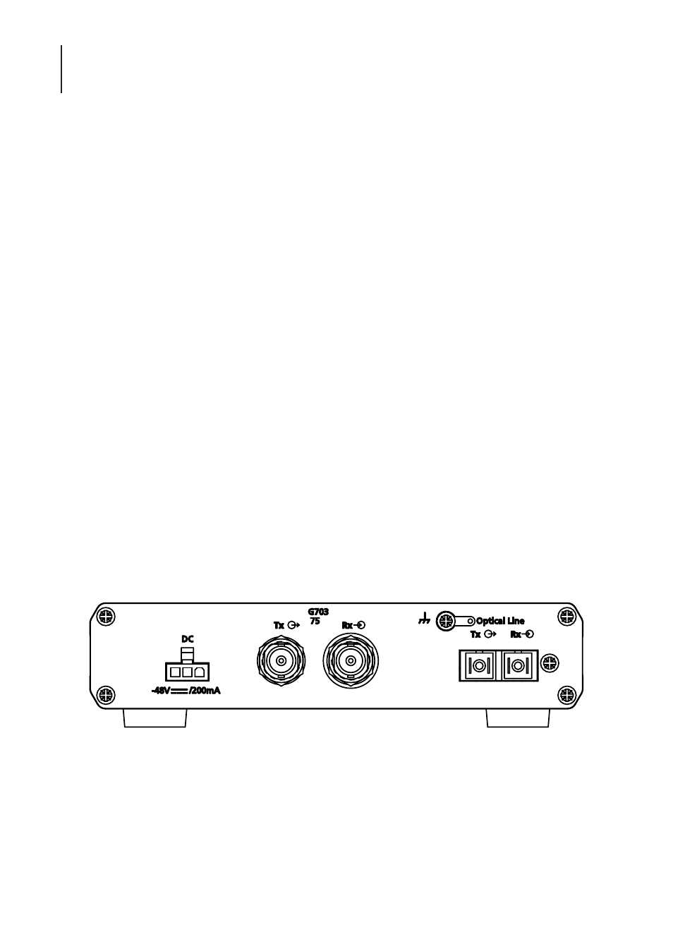
3.2.1
DC VARIANT
The DC unit
Figure 5 OM25 DC G.703 75
Ω
Ω
with SC Optical Connectors
Ω