Ensemble Designs BrightEye 55 Genlockable Sync Generator and Test Signal Generator User Manual
Page 7
TM
BrightEye 55
BrightEye 55 - Page 7
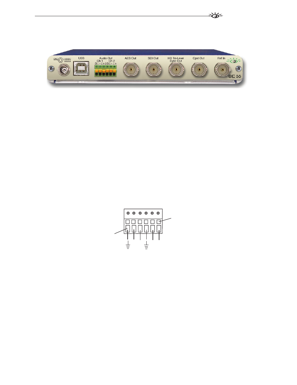
REAR CONNECTORS
All connections to the BrightEye 55 converter are made on the rear of the unit.
Refer to the illustration below.
Power Connection
Connect a modular power supply to the 12 volt DC power input connection on the
far left of the unit. Use the locking ring to secure it.
USB Connector
The USB connector is used to provide more comprehensive control, diagnostics,
and upgrades to the unit from a PC or Mac. Use the BrightEye Control applica-
tion included on CD-ROM to make adjustments as described in the
OPERATION
section of this user guide.
Audio Out
The
Audio Out provides two channels of an analog audio reference tone. Wiring
is done by inserting a 6 pin connector provided with the unit. Analog reference
levels can be configured from the BrightEye Control application. The pinouts for
the audio connector provided are shown in the diagram below.
To connect audio to this connector type, strip the audio wire to about 3/8” (8 mm).
Solder tinning is not required. Push the wire into the opening at the bottom of the
connector to seat the connection. This will snap the wire into place.
To remove the wire, push in the pin above the connection with a small pointed
tool. This will release the wire from the connector.
Balanced Analog Audio Connection – to connect the audio output to an audio
XLR connector, connect the pins as follows:
• Attach Ground from Pin 1 of the Audio Out to Pin 1 of the XLR.
• Attach the + (plus) signal from Pin 2 of the Audio Out to Pin 2 of the XLR.
• Attach the – (minus) signal from Pin 3 of the Audio Out to Pin 3 of the XLR.
BrightEye 55 Rear Connectors
+
-
-
+
Ch 2
Ch 1
Push in to release
Pin 1
Audio Output Connector