Verifying the installation – H3C Technologies H3C S12500 Series Switches User Manual
Page 15
12
2.
Connect one end of the black DC power cord to the RTN(+) terminal on the power strip, and fasten
the screw.
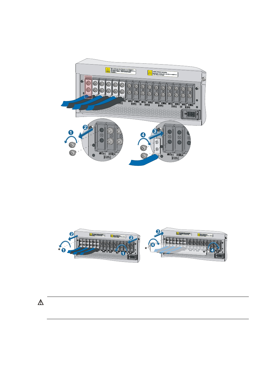
Figure 17 Connecting the DC power cord to the grounding strip
3.
Connect the other end of the DC power cord to the power source:
{
Connect the other end of the blue DC power cord to the –48 VDC power source.
{
Connect the other end of the black DC power cord to the RTN(+) terminal that provides power
to the switch.
4.
Put the protection cover on the wiring terminals.
Figure 18 Installing the protection cover
Verifying the installation
WARNING!
Each of the S12508 has one power switch, and an S12518 has two power switches. Make sure you have
turned off the power before checking the installation to avoid bodily injury and switch damage.
After the installation is completed, verify the installation against the following list. Make sure all check
results are positive.