Evb configuration example, Network requirements, Configuration procedure – H3C Technologies H3C S10500 Series Switches User Manual
Page 20
13
Task Command
Display VSI interface information.
display evb vsi [ verbose ] [ interface interface-type { interface-number
| interface-number:channel-id |
interface-number:channel-id.vsi-local-id } ]
Display information about an
S-channel interface, S-channel
aggregate interface, VSI interface, or
a VSI aggregate interface.
display interface [ s-channel | schannel-aggregation ] [ brief [ down ] ]
display interface [{ s-channel | schannel-aggregation }
[ interface-number:channel-id |
interface-number:channel-id.vsi-local-id ] ] [ brief [ description ] ]
Clear statistics for an S-channel
interface, S-channel aggregate
interface, VSI interface, or a VSI
aggregate interface.
reset counters interface [ { s-channel | schannel-aggregation }
[ interface-number:channel-id |
interface-number:channel-id.vsi-local-id ] ]
EVB configuration example
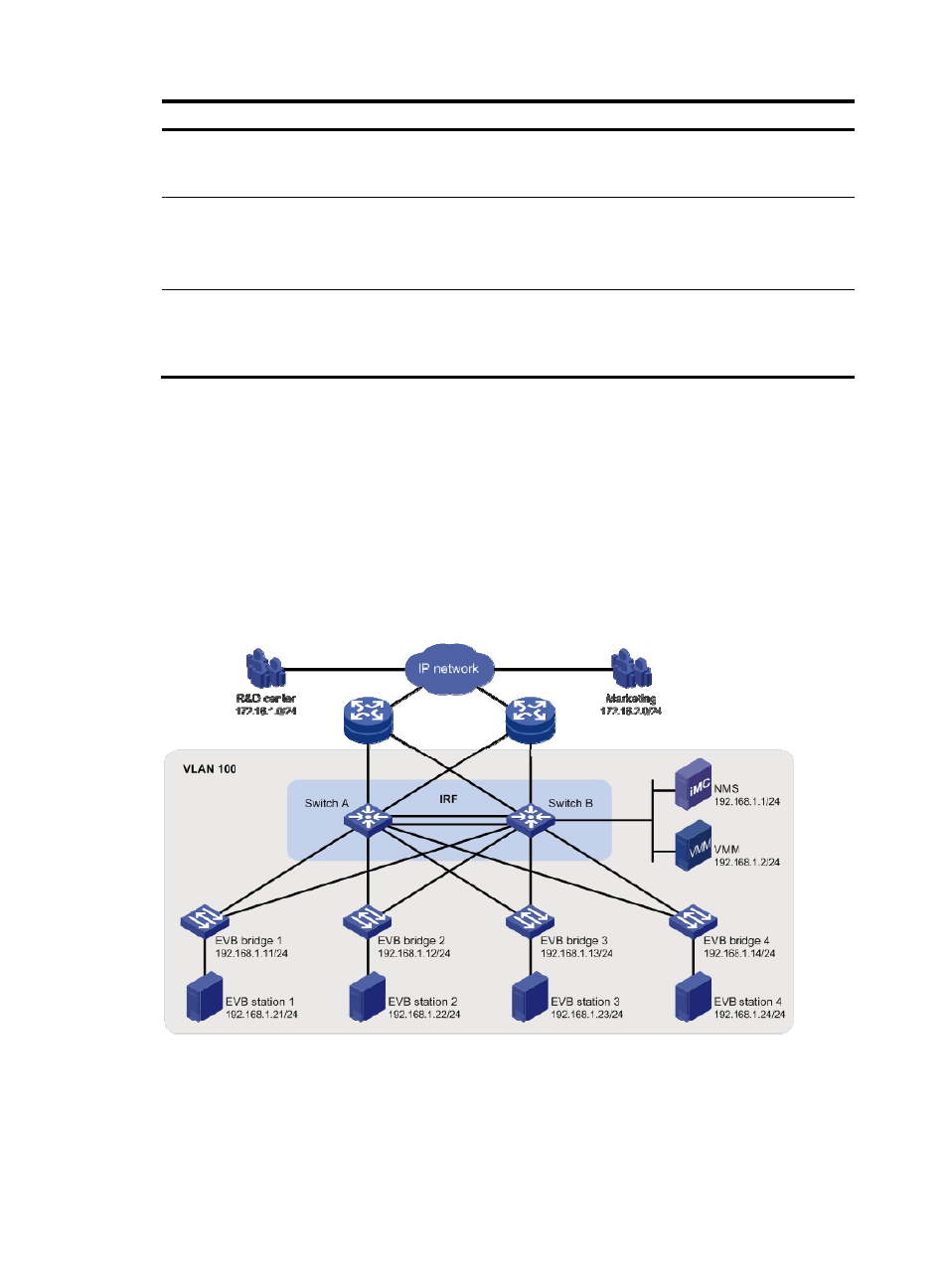
Network requirements
As shown in
, the Layer 2 network of a data center comprises two switches that form an IRF fabric,
four EVB bridges, and four EVB stations. They communicate within VLAN 100.
Create VM 1 with MAC address 0050-5684-21C7 on EVB station 1, and set VM1 as the FTP server with
a CIR of 2048 kbps and a PIR of 4096 kbps. Only the R&D center is allowed to access the network.
Figure 3 Network diagram
Configuration procedure
This section only contains EVB configurations.
1.
Configure the EVB bridge:
# Create VLAN 100 on EVB bridge 1.