H3C Technologies H3C S5800 Series Switches User Manual
Page 17
Advertising
13
Step4
Connect the AC power source to the RPS unit.
Step5
Check that the PWR LED on the front panel of the RPS unit lights
up.
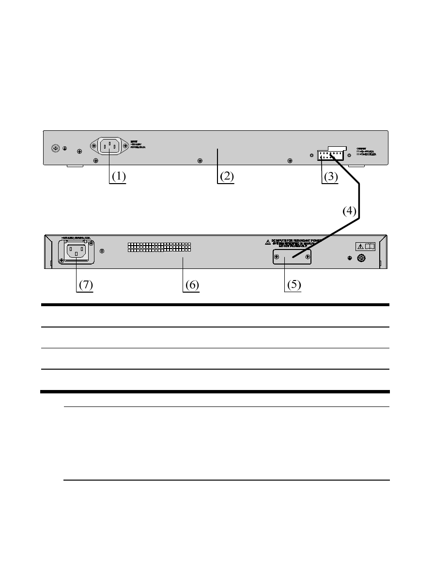
Figure 7 Connect the RPS unit to a switch
(1) RPS AC input
(2) RPS rear panel
(3) RPS DC output
(4) DC power cable (optional)
(5) Switch redundant power supply input
(6) Switch rear panel
(7) Switch AC input
NOTE:
The OUT LED lights up only when the RPS800-A switches to the RPS
output state. When the RPS800-A works in the monitoring mode, its
OUT LED stays off.
Advertising
This manual is related to the following products: