Grass Valley 2020DAC D-To-A User Manual
Page 21
2020DAC Instruction Manual
15
Configuration and Adjustments
The
CH 1/2 OUTPUT MODE
display allows you to set the desired output mode
of the module from the selections listed in
. After making the selec-
tion, click the
APPLY
button to activate it.
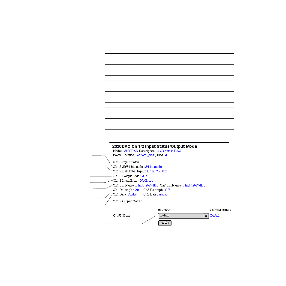
Figure 10. 2020ADC Ch1/2 Input Status/Output Mode
Table 7. Ch 1/2 and Ch 3/4 Remote Control Output Modes
Mode Name
Mode Description
Default
Factory default with no phase inversion, channel swapping or summing.
L/R Swap
Swaps left and right channel outputs.
L/R Invert
Both left and right channel outputs phase inverted.
L Invert
Left channel output phase inverted.
R Invert
Right channel output phase inverted.
R Mono (R to L/R)
Right channel to both channel outputs.
L Mono (L to L/R)
Left channel to both channel outputs.
L plus R to L/R
Left plus right to both channel outputs.
L minus R to L/R
Left minus right to both channel outputs
L plus R, L minus R
Left plus right to left channel output and left minus right to right channel output.
(L plus R) Inv to L/R Left plus right to both channel outputs with both channel outputs phase inverted.
AES Silence
AES silence on both left and right channel outputs.
1K@ -20dBFS
Tone to both channel outputs.
Jumper setting for
20- or 24-bit DAC operation
Jumper settings for
output levels
Jumper setting for
balanced or unbalanced inputs
Select the output mode
for Ch 1/2 from values
listed in table in text.
Input sample rate
Input error status
Type of incoming data
De-emphasis status