Grass Valley 8900GEN-SM User Manual
Page 22
22
8900GEN-SM — Instruction Manual
8900GEN-SM Applications
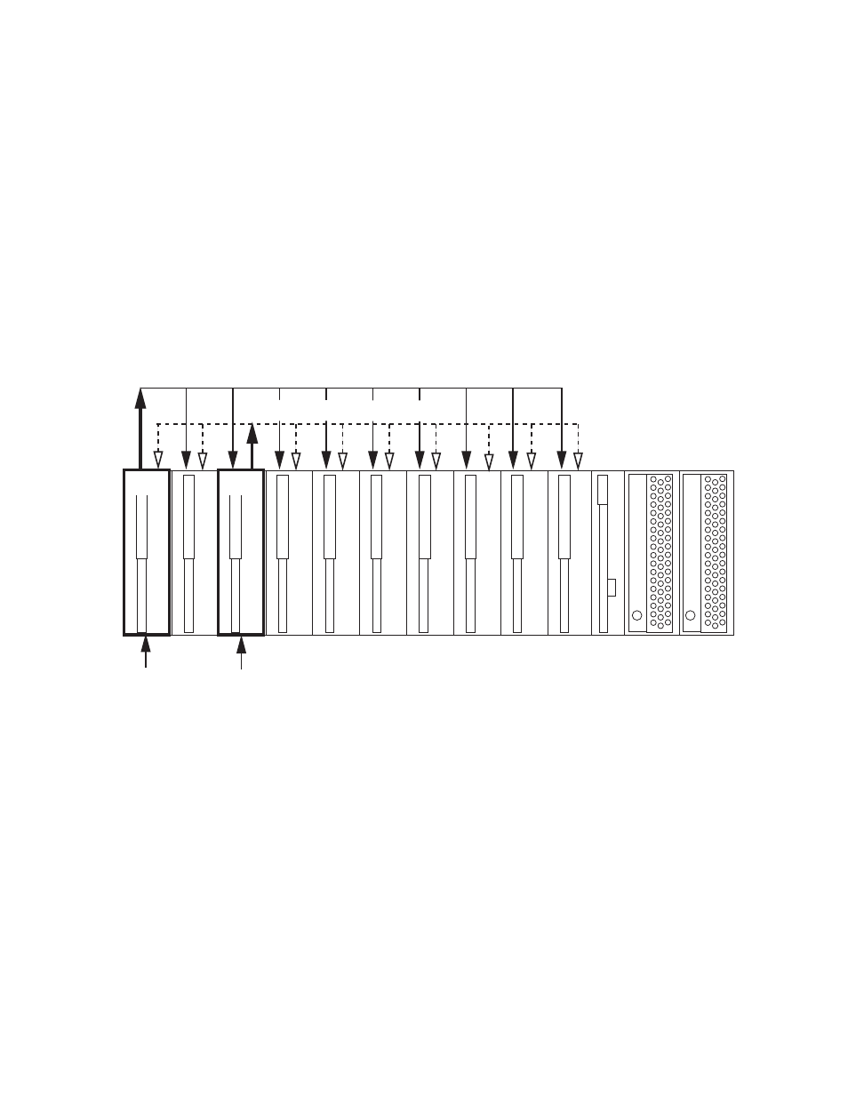
Module Placement and Cabling For Redundant Reference
As shown in the diagram in
, a house reference is connected to the
Genlock Loop of the host module in slot 1 with an 8900GEN-SM sub-
module installed. The host module is jumpered for outputting Frame Bus 1.
A separate redundant backup of the house reference is connected to the
Genlock Loop of the module with an 8900GEN-SM installed in slot 3. This
module is jumpered to output Frame Bus 2. This slot configuration is fixed.
The other modules in the frame are configured for Primary and Secondary
redundancy in system configuration. These modules do not require an
8900GEN-SM module to be installed and can accept the frame bus refer-
ences.
Figure 6. Primary and Secondary Genlock Timing Sources
8488_01
Frame Bus 1 (Primary Reference)
Slot 1
Slot 3
Frame Bus 2 (Secondary Referrence)
House
Reference 1
House
Reference 1
Backup