To select the lowest input level range that – Grass Valley 8920ADC v.2.0 User Manual
Page 15
8920ADC Instruction Manual
9
Configuration
Setting Maximum Operating Level
Once you have determined the proper coarse level jumper setting, perform
the following steps:
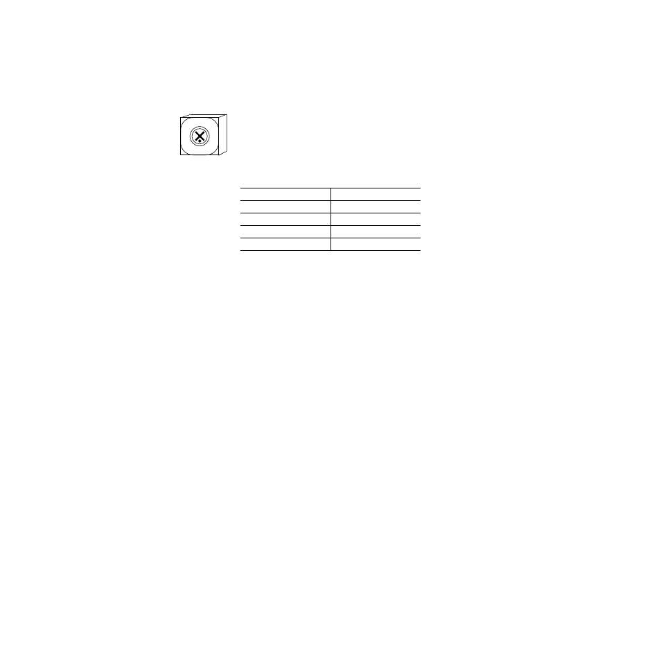
1.
Set the Function Rotary Switch to the position marked 0 as shown at
left.
2.
Remove the module from the frame and set jumpers on JP5 and JP6 to
the jumper setting that you determined using
.
3.
Return the module to the frame.
Using Level Gain Toggle Switches
Note
The toggle switches change input levels by increments of approximately
0.1 dB when held momentarily. Holding the switch up or down for about 1
second activates a continuous change mode that ramps the change rate from
about 0.1 dB per second to 0.6 dB per second. The yellow CONF LED will
flash slow (0.1 dB rate) or fast (0.6 dB rate) to indicate the change rate.
There are three ways to adjust the gain toggle switches to the proper level:
■
Apply the maximum level to the input (example +24 dBu) and monitor
the AES output with a meter that indicates digital level in dBFS and
adjust the toggle switch for each channel until the meter indicates
0.0 dBFS.
Because the toggle switches have a resolution of 0.1 dB, you may not be
able reach 0.0 dBFS exactly. Use the closest negative setting possible.
■
Apply an audio level that is -20 dB below the maximum level, (+4 dBu
for the example, +24 dBu -20 dB = +4 dBu) and adjust the AES output
as indicated on a digital audio meter to -20 dBFS.
If you have no meters calibrated in dBFS you can use the tone output
position to compare with the output level. Tone output is position E on
the Function Switch and outputs a 1 kHz tone at -20 dBFS. Note the
internal tone level indication while monitoring the AES output and
switch back to 0 or F position on the Function Switch, then adjust the
gain toggle switch to the same level as the internal tone level.
Table 4. Jumper Coarse Level Settings for 0.0 dBFS Output
Input Level
JP5/JP6 Jumper Position
12 to 16 dBu
Pins 1 and 2
16 to 19 dBu
Pins 2 and 3
19 to 25 dBu
Pins 4 and 5
25 to 28 dBu
Pins 5 and 6
012
34
5
67
89AB
C
D
EF
Default
Position