E the left ten locations. refer to – Grass Valley 8920ADC v.2.0 User Manual
Page 9
8920ADC Instruction Manual
3
Installation
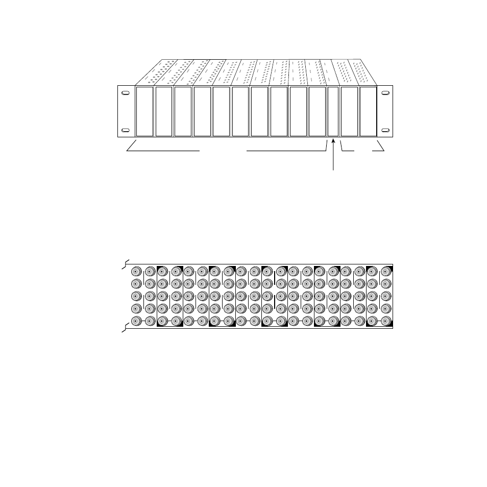
Figure 1. 8900 Series Frame
8900 modules are interchangeable within the module cells. There are 10
BNC connectors in each cell’s I/O group. The functional assignment of
each connector in a group is determined by the module that is placed in
that cell. The maximum number of modules an 8900 frame can accept is ten.
illustrates the rear connector plate for an 8900 Series frame.
Figure 2. 8900 Series Frame Rear Connector
To install a module in the frame:
1.
Insert the module, connector end first, with the component side of the
module facing to the right and the ejector tab to the top.
2.
Verify that the module connector seats properly against the backplane.
3.
Press the ejector tab in to seat the module in place.
Frame Monitor Module or
Network Interface Module
Any 8900 Module
Power
Supplies
(only)
0595-04r1
0595-03
J1
J2
J3
J4
J5
J6
J7
J8
J9 J10
IN
DA1
J2
J4
J6
J8
J1
J2
J3
J4
J5
J6
J7
J8
J9 J10
IN
DA3
J1
J2
J3
J4
J5
J6
J7
J8
J9 J10
IN
DA5
J1
J2
J3
J4
J5
J6
J7
J8
J9 J10
IN
DA2
J1
J2
J3
J4
J5
J6
J7
J8
J9 J10
IN
DA7
J1
J2
J3
J4
J5
J6
J7
J8
J9 J10
IN
DA9
J1
J2
J3
J4
J5
J6
J7
J8
J9 J10
IN
DA4
J2
J4
J6
J8
J1
J2
J3
J4
J5
J6
J7
J8
J9 J10
IN
DA6
J2
J4
J6
J8
J1
J2
J3
J4
J5
J6
J7
J8
J9 J10
IN
DA8
J2
J4
J6
J8
J1
J2
J3
J4
J5
J6
J7
J8
J9 J10
IN
DA10
O
U
T
O
U
T
O
U
T
O
U
T
O
U
T
O
U
T
O
U
T
O
U
T
O
U
T
O
U
T