Grass Valley 8920ADC v.2.0 User Manual
Page 19
8920ADC Instruction Manual
13
Configuration
Audio Control and Status
The Audio Control and Status display provides controls for setting the fol-
lowing parameters on the 8920ADC module:
■
Operational (output) mode, and
■
Fine adjustment of output levels.
Set the Operational Mode for the desired output of the module from the
thirteen selections listed below in
. After making the selection, hit the Apply button to
activate it.
Fine gain adjustment of the module output levels can be done with this dis-
play. Coarse gain levels must first be set up using the on-board jumpers JP5
and JP6 as described in
cedures given there for adjusting the output levels using the fine gain
adjustments described below.
Adjust the fine gain in either Numeric or Sliders mode as shown in
. The single arrows increment the value by 1x and the double
arrow will increment the value by approximately 10x. These controls will
allow you ± 6.0 dB of fine adjustment range.
Note
In Numeric mode only, values selected with the single or double arrow keys
will be enabled immediately. All other display entries, including typed in
values, require pressing Apply before the selection is enabled.
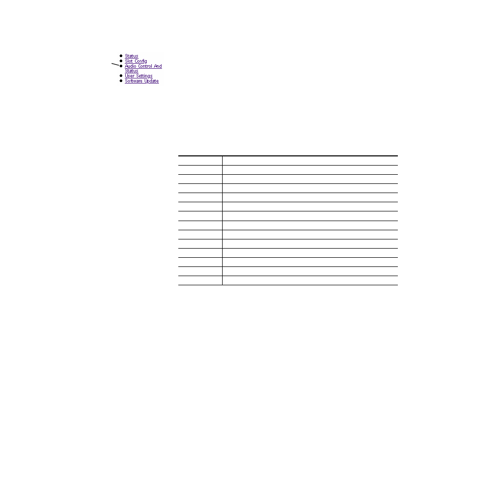
Table 6. Remote Control Output Configuration Modes
Mode Name
Mode Description
Default
Factory default with no phase inversion, channel swapping or summing.
L/R Swap
Swaps left and right channel outputs.
L/R Invert
Both left and right channel outputs phase inverted.
L Invert
Left channel output phase inverted.
R Invert
Right channel output phase inverted.
R Mono (R to L/R)
Right channel to both channel outputs.
L Mono (L to L/R)
Left channel to both channel outputs.
L plus R to L/R
Left plus right to both channel outputs.
L minus R to L/R
Left minus right to both channel outputs
L plus R, L minus R
Left plus right to left channel output and left minus right to right channel output.
(L plus R) Inv to L/R Left plus right to both channel outputs with both channel outputs phase inverted.
AES Silence
AES silence on both left and right channel outputs.
1K@ -20dBFS
Tone to both channel outputs.
Use
This
Link