Connecting to the camera system, Page 9 – Grass Valley 3-CCD ANALOG CameraMan Rev.B User Manual
Page 12
Page 9
Connect Your 3-CCD Camera System
Connecting To The Camera System
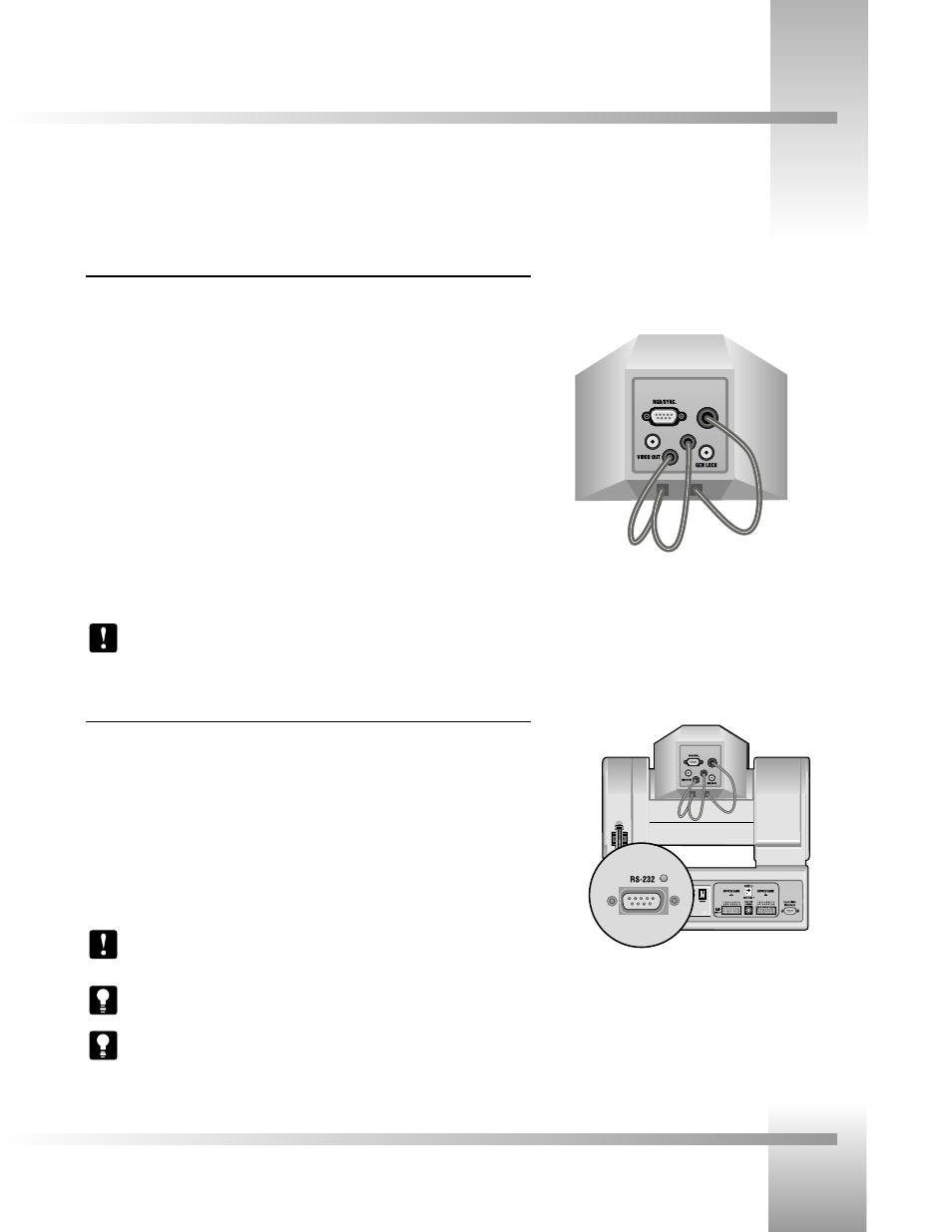
Connecting The Video, RGB/Sync and Genlock Output (if needed)
RGB / SYNC: If your system requires RGB or component video output, use a DB9 to BNC
breakout cable to connect the DB-9 port labeled RGB / SYNC to an appropriate video input on
your network. The DB-9 pin assignments are:
Pin 1
Signal
Pin 2
Ground (VBS)
Pin 3
RED (R-Y) output
Pin 4
GREEN output
Pin 5
BLUE (B-Y) output
Pin 6
VBS (Y) output
Pin 7
SYNC output
Pin 8
Ground (SYNC)
Pin 9
NC (C output)
VIDEO OUT: For aux composite video output, connect the BNC-type connector labeled
“VIDEO OUT” to an alternate video input in your network using a standard BNC cable.
GEN LOCK: Connect the BNC-type connector labeled “GEN LOCK” to your network’s Video
Timing Source (Sync Generator) using a standard BNC cable.
Note: A Camera Control Keypad, Tracking System Keypad, or CameraMan Shot
Director are necessary to adjust the H. (horizontal) and SC (sub-carrier) phases, as well
as configure the RGB/Sync Connection.
Connecting To The RS-232 Port
The General Pan/Tilt Camera System provides for RS-232 communications using the DB-9 jack
on the back of the camera, labeled RS-232. This RS-232 port can be used to control the
CameraMan Camera from external devices such as a PC or other vendor control system (i.e.:
AMX, Crestron). Connect to this port using a standard computer cable with a DB-9 connector.
When used with a CameraMan SHOT Director, this port operates at 19,200 Baud, No Parity
and software hand-shaking using a High Reliability protocol. Otherwise, the port
operates at 9600 Baud, No Parity, and software hand-shaking using a High
Reliability or Basic protocols.
Note: Verify which protocol is being used by checking the PROTOCOL switch on the
Camera (see page 12).
Tip: The COM light above the RS-232 port is used to indicate communication activity.
Tip: For the DB-9 pinout port information, see the Appendix D: PIN-OUT DIAGRAMS
on page 17 .
RS-232 Port on the back of the
3-CCD CameraMan
Back of 3-CCD Camera Shroud