Switch configuration, Page 12 – Grass Valley 3-CCD ANALOG CameraMan Rev.B User Manual
Page 15
Page 12
CameraMan
®
3-CCD Camera System Installation and Operations Manual
Switch Configuration
Now that you have connected your CameraMan to your power supply and control devices, you need to configure the camera to
work in your specific application. To begin, remove the configuration plate on the back right side of the camera by removing the
two screws holding it in place. Behind it, you’ll see all the configuration switches. From left to right, they are:
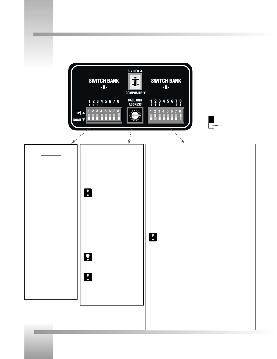
Switch Bank B
Dip Switch 1 (Protocol)
Select the communication protocol which will be used by the RS-232 and RS-485
ports on the camera. The High Reliability protocol includes some advanced error
checking that is not performed in the Basic protocol. (factory default: DOWN)
Dip Switch 2 (Camera Data Local/Remote Select)
When this switch is DOWN, the camera will receive data from a local source. When
it us UP, the camera will receive data from a remote source, such as a joystick.
(factory default: DOWN)
Dip Switch 4 (RF Command)
When this switch is DOWN, the camera responds to commands sent from an RF
Keypad. When it is UP, the RF receiver in the camera is disabled and the camera
cannot receive commands directly from a wireless keypad. (factory default: DOWN)
When using multiple cameras networked on the RS-485 bus, only one
camera should have its RF receiver enabled. Set switch 4 on the other
cameras to UP.
Dip Switch 5 (Preset Save)
Use this switch to determine how the preset settings will be saved. DOWN saves
your Manual Gain, Iris, and Focus settings. UP saves only the Auto settings for
presets and autoTRACK Views. (factory default: DOWN)
Dip Switch 8 (Interlink)
Use this feature in multi-camera applications. When it is DOWN, all commands will
be passed onto the RS-485 communication bus to the appropriate camera. For a
single-camera application, the setting of this switch does not matter. (factory
default: DOWN).
Switch Bank A
Dip Switch 2 (SC-Coarse)
This switch is used to configure the
SC-PHASE (coarse) to either 0°
(DOWN) or 180° (UP). (factory
default: DOWN)
Dip Switch 7 (Baud Rate)
This switch is used to configure the
camera’s Baud Rate for the RS-232
and RS-485 ports. Switch UP for
19,200 and DOWN for 9600. (factory
default: UP)
Dip Switch 8 (Memory)
For the majority of applications, this
switch should be set to UNLOCK (UP).
When DOWN, all programmed
features are locked and cannot be
overridden. (factory default: UP)
Central Control Switches
Video Select (Composite/S-Video)
Set the video source switch to the down
position to select the COMPOSITE VIDEO OUT
option, or up to select the S-VIDEO OUT
option.(Factory Default: COMPOSITE)
You must choose either the
Composite, or S-Video format. They
cannot be used simultaneously.
Base Unit Address
Use the 16-position rotary switch labeled BASE
UNIT ADDRESS to set the unique identification
number for this CameraMan. If using the
optional Keypad, Shot Director, or another
control system, refer to the documentation
provided with those accessories for proper
configuration.
For setting up a camera network,
see page 15, Appendix B: MULTIPLE
CAMERA APPLICATIONS.
All switches not discussed on this
page should remain in the down or
OFF position.
Example: Switch in
the down position