Cameraman configuration switches – Grass Valley 3-CCD ANALOG CameraMan Rev.B User Manual
Page 9
Page 6
CameraMan
®
3-CCD Camera System Installation and Operations Manual
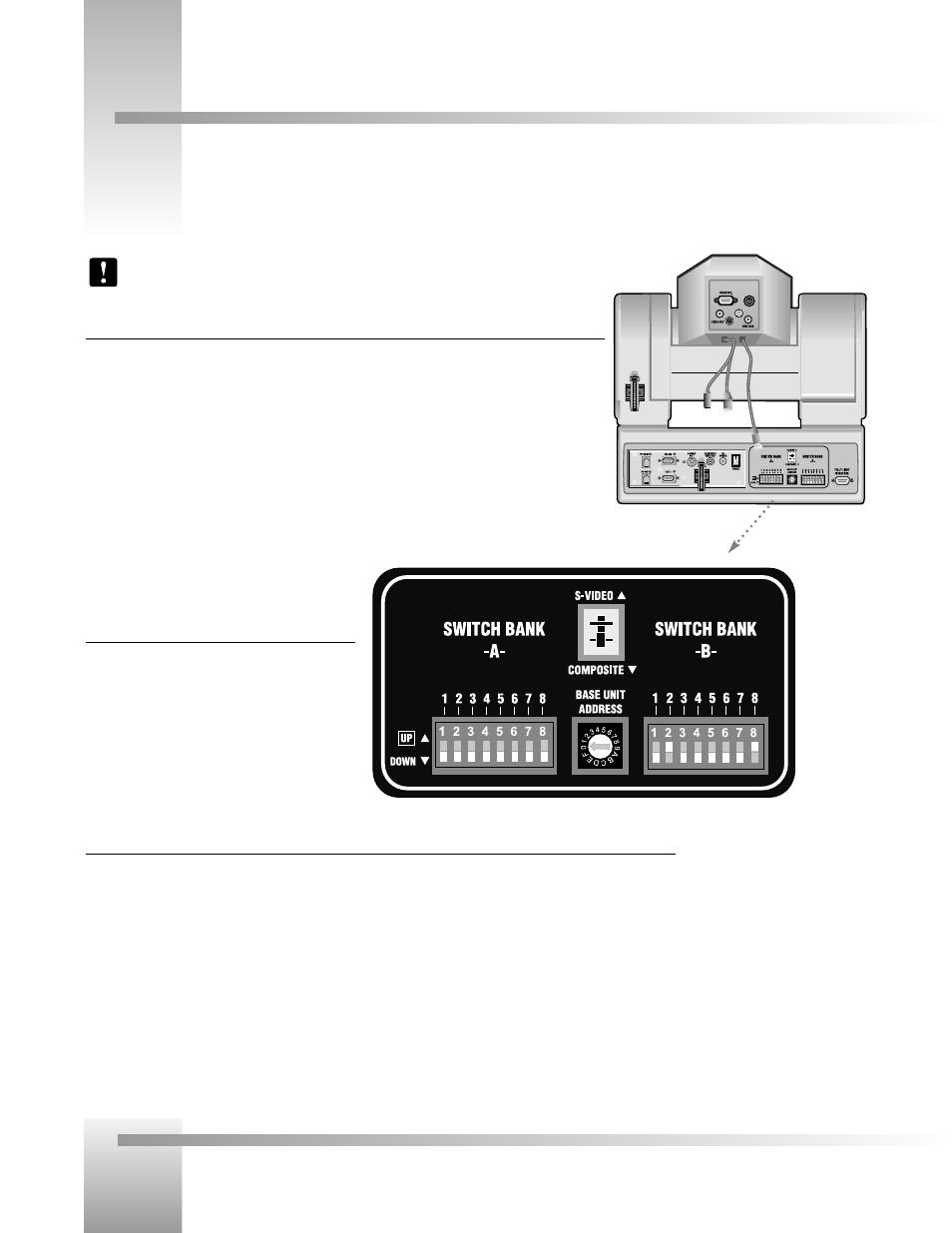
Switch Bank A
▼
▼
Switch 2 (Sub-Carrier Coarse Adjustment Switch)–Used to change the
sub-carrier phase from 0° to 180°.
▼
▼
Switch 7 (Baud Rate Switch)– Used to change the camera’s Baud Rate.
▼
▼
Switch 8 (Memory Lock Select Switch)–Can be used to prevent programmed settings from being
accidentally overridden.
▼
▼
Switches 1, 3, 4, 5 and 6— Reserved for future use.
Center Control Switches
▼
Video Select Switch–Used to select the Video
Output Format. This can be configured as either
Standard Composite or S-Video.
▼
▼
Base Unit Address–Used to configure the address
of the Camera.
Switch Bank B
▼
▼
Switch 1 (Protocol Select Switch) – Used to select the type of Protocol being used for RS-232 and RS-485
communications. This can be configured as either Basic or High Reliability.
▼
▼
Switch 2 (Camera Data Local/Remote Select) – Used to determine whether the camera will receive data from a local
source or a remote source, such as a joystick.
▼
▼
Switch 4 (RF Commands Switch) – Used to enable or disable the RF Receiver in the CameraMan camera.
▼
▼
Switch 5 (Preset Save) - Used to determine how the preset settings will be saved.
▼
▼
Switch 8 (Interlink Switch) – Used to disable commands from being sent on the RS-485 bus to other CameraMan
devices.
▼
▼
Switches 3, 6 and 7— Reserved for future use.
CameraMan Configuration Switches
Behind the configuration plate on the lower left side of the back of your CameraMan is the configuration panel. These DIP and
rotary switches allow you to link the camera’s settings to other components in your system.
Back of 3-CCD
CameraMan
Note: After changing any switch’s settings, turn the camera off, then back on to activate
the change.