Figure 44. port backplane cabling, Ports 1 to 32 – Grass Valley Concerto Routing Matrix v.1.8.1 User Manual
Page 89
Concerto — Installation and Service Manual
89
Cabling
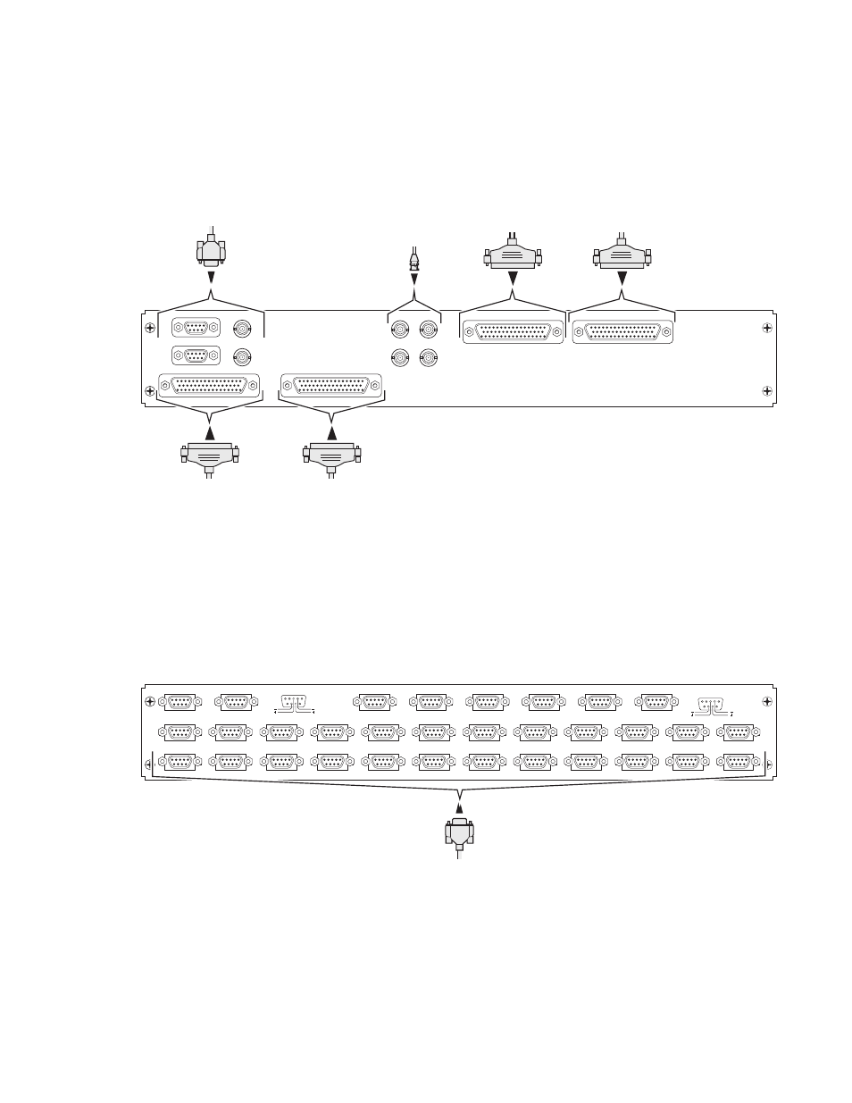
shows the cabling for the Digital Audio Balanced 50 pin D back-
plane. This backplane is used by the Digital Audio (AES) module and the
Time Code module.
Figure 43. Digital Audio 50 Pin D Backplane Cabling
shows the cabling for the Port backplane. This backplane is used
by the Port module.
Note
This backplane meets the industry standard. Verify that you have the correct
pinouts (see
) and the correct Port module (see
Figure 44. Port Backplane Cabling
MON OUT
MON IN
IN 25-32
IN 9-16
OUT 9-16
OUT 25-32
8138_00_26r0
EXP IN 1 & 2
EXP OUT 1 & 2
MON IN
MON OUT
INPUTS
1-16
INPUTS
17-32
OUTPUTS
1-16
OUTPUTS
17-32
8138_03_93r1
Ports
1 to 32
1
4
3
2
6
5
8
7
10
9
13
12
16
15
19
18
22
21
225
24
28
27
30
29
32
31
11
14
17
20
23
26
C O N T R O L L I N G
CONTROLLED
PORT BACKPLANE
T x
R x
T x
R x
1
1