5 audio output connectors 1+2, 6 data / s9000 connector, 7 network connector – Grass Valley HD Wireless User Manual
Page 72: 8 reference input connectors (2x)
72
HD Wireless User’s Guide (v6.2)
Chapter 6 - Connectors
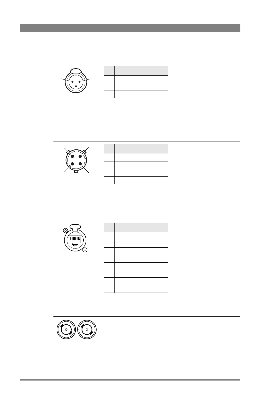
6.3.5 Audio output connectors 1+2
6.3.6 Data / S9000 connector
6.3.7 Network connector
6.3.8 Reference input connectors (2x)
Pin Description
1
Audio shield
2
Audio output (+)
3
Audio return (-)
XLR 3-pin male
Nominal level 0dBu (+6dBu
selectable)
Shield of cable directly to the
connector housing.
If the same signal is applied at pin2 of
Audio input 1 and 2 (WCA), then
Signal at pin 2 of audio output 1 is in
phase with signal at pin 2 of audio
output 2.
3
2
1
Pin Description
A
S9000 Data
B
Data Not
C
Not connected
D
Shield
4-pin souriau
connector
Shield of cable to the pin marked
housing.
Note: a legacy Series 9000 control
panel can be connected using a 4-pin
souriau cable.
D
B
C
A
Pin Description
1
Transmit data + (TX+ )
2
Transmit data - (TX-)
3
Receive data+ (RX+)
4
no connection
5
no connection
6
Receive data - (RX-)
7
no connection
8
no connection
Ethernet 10Base-T, 100Base-TX
compliant with IEEE-802.3 (edition
2000)
8-pin standard
RJ-45 ethernet
connector
This BNC connector accepts either a 1.0 Vpp CVBS SDTV composite or a 1.0 Vpp
TLS-HDTV reference (should include H and V synchronization) signal to the
camera for genlocking.
Note: The second connector should be terminated with 75
if the signal is not
looped through.
BNC connectors