Grass Valley Kaleido-Modular-X v.7.70 User Manual
Page 52
48
Setting Up Your Kaleido-Modular-X System
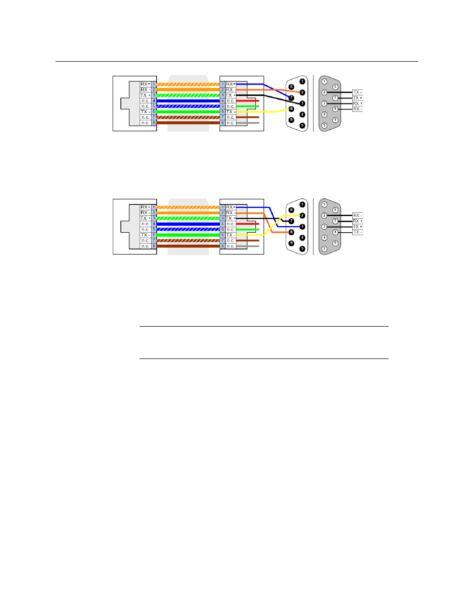
RS-422 Connection Diagram
Standard wiring between multiviewer and devices wired to SMPTE “slave” specification (e.g. most
routers, Ross Synergy switchers, Nevion ETH-CON)
Standard wiring between multiviewer and devices wired to SMPTE “master” specification (e.g. Philips
Jupiter router control system, Grass Valley Presmaster PCS)
For more information about the RS-422 specifications, see the “Communication” section in
the Specifications chapter of the Kaleido-Modular-X Hardware Description & Installation
Manual. For more information about the RS-422 serial connections, see the “Serial
Connections” section in the Routers chapter of the Kaleido-Modular-X User’s Manual.
Note:
The two RS-422 ports on the multiviewer side have no ground pin.
Using the appropriate DE-9S-to-RJ-45 adapter, an external device should be
able to communicate with a multiviewer despite the lack of a ground.
Pinout of each RS-422
port’s RJ-45 connector
on the multiviewer
Pinout of straight adapter (Grass
Valley part no. 1737-3000-102)
RJ-45
DE-9 male DE-9 female
Pinout of RS-422
connector on SMPTE
slave device
Pinout of each RS-422
port’s RJ-45 connector
on the multiviewer
RJ-45
DE-9 male DE-9 female
Pinout of crossover adapter (Grass
Valley part no. 1792-3700-100)
Pinout of RS-422
connector on SMPTE
master device