Grass Valley Kaleido-X (7RU) Quick v.7.80 User Manual
Page 18
6
Setting Up Your Kaleido-X (7RU) Multiviewer
Physical Setup
The Kaleido-X has been configured to automatically detect the resolution of any
connected display. If the required information is not available, then a fall-back
resolution of 1280 × 1024 @ 60 Hz is used.
2 Connect at least one output of the Kaleido-X to displays that support this resolution
• Monitor wall displays: Connect the multiviewer’s DVI-D OUT outputs to the
displays.
• Broadcast monitors: If your installation involves broadcast monitors, connect
them to the appropriate SDI outputs. It is also possible to connect SDI outputs to a
router. Refer to Configuring the HD-SDI Monitoring Output Format
, in the Kaleido-X
User’s Manual, for instructions on setting the scan format.
If you wish to use a different resolution, see
Changing the Output Resolution
below, for
detailed instructions.
3 Connect one or more video sources to the frame.
4 Make the network and other connections as shown in the cabling diagram (see
Connect a client PC, the Kaleido-RCP2, one or more Audio Bridge Terminals, and every
output module to a dedicated 100Base-T Ethernet switch. You can also connect a
mouse and a keyboard to your Kaleido-RCP2.
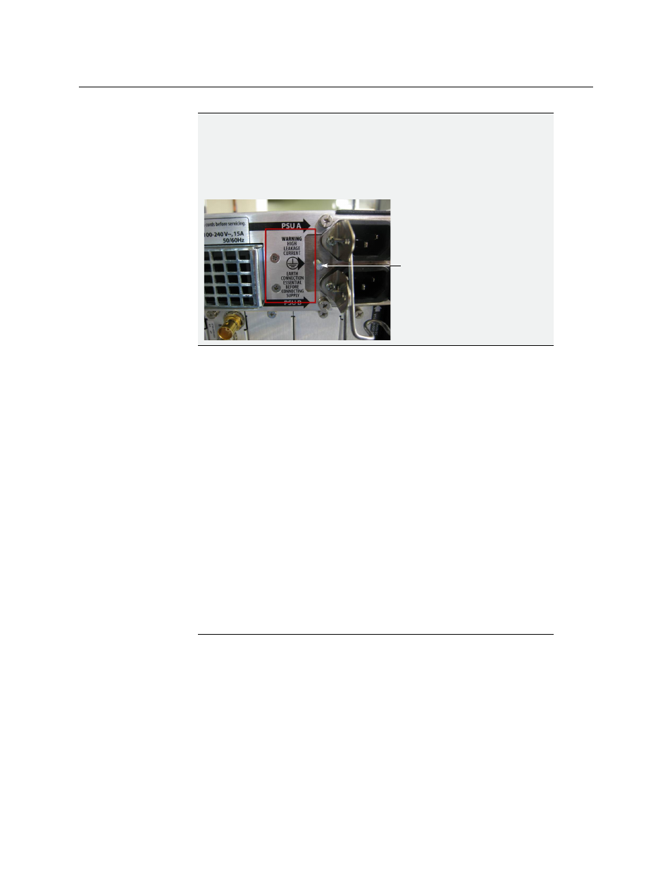
IMPORTANT
There are two different models of 7RU frames, and two models of power
supplies. If you have a frame model KXA-FR7-B (with the corresponding
KXA-PSU-7-B power supply), you must ensure that a ground cable (not
included) is connected between the frame and the rack before powering
up the unit.
Notes
• The Kaleido-RCP2, and Audio Bridge Terminal (ABT) are optional devices,
and may not have been shipped with your Kaleido-X (7RU) system. For
information on these and other Kaleido-X options, please contact your
Grass Valley sales representative.
Connect a ground cable
and the rack
between this stud