Audio clock signals, Chapter 3 mechanical installation – Grass Valley PDR100 User Manual
Page 64
Chapter 3 Mechanical Installation
3-40
PDR100 Installation
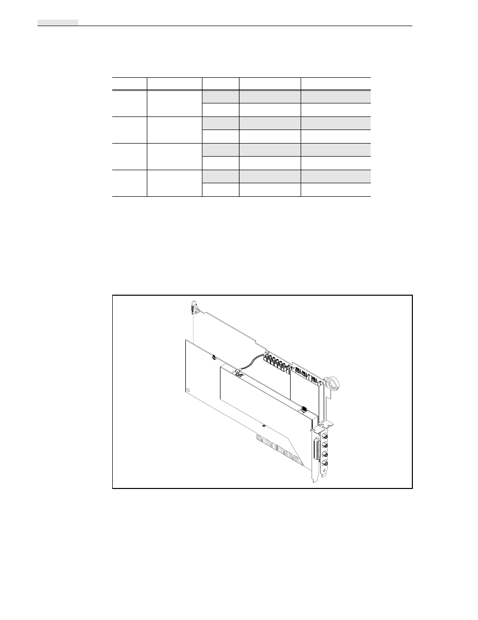
Audio Clock Signals
The only clock signals available on the Analog Composite Output circuit board are
system clocks (27 MHz). There are four identical buffered clock signals available,
enough to have one clock signal for each of the output channels. In most cases not all
will be used. The example shown in Figure 3-37 has only one Audio I/O circuit board,
which is located adjacent to the Composite Analog Output circuit board. With longer
cables, the clock signals can be routed to other Audio I/O circuit boards located some
distance from the Analog Composite Output circuit board.
Figure 3-37. Audio Clock from Analog Composite Output Circuit Board
J3
Channel 1 Filter
Output
Jumpered
Jumpered
Corrected
Open
Open
J6
Channel 2 Filter
Output
Jumpered
Jumpered
Corrected
Open
Open
J15
Channel 3 Filter
Output
Jumpered
Jumpered
Corrected
Open
Open
J14
Channel 2 Filter
Output
Jumpered
Jumpered
Corrected
Open
Open
Table 3-15. Analog Composite Output Plug Jumpers (Continued)
Jumper
Name
Position
Factory- Installed
Operation