Output reclocker bypass settings, Installation 134 planning and installation manual, Switch settings are shown in table 24 – Grass Valley Trinix v.2.4.1 User Manual
Page 134
Advertising
Installation
134
Planning and Installation Manual
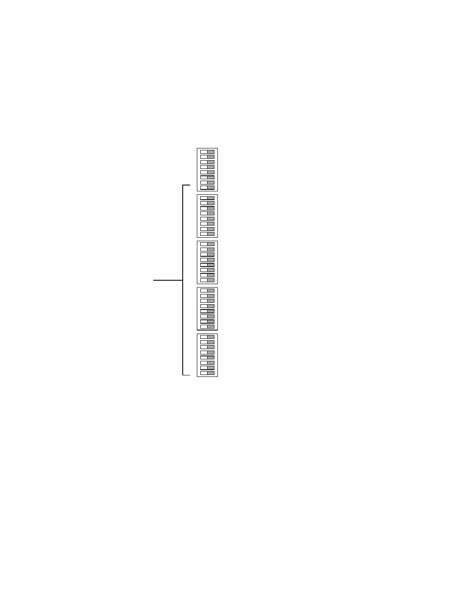
Output Reclocker Bypass Settings
The following discussion applies to units equipped with the HO-33110
HD or the HO-33120 SD/HD Output Boards.
Front edge DIP switches S5-8 and S1 through S4 on these output boards
are used to control reclocking.
Figure 71.
Switch settings are shown in
.
SYNC SEL A
SYNC SEL B
AUTO RCLK
Open
Closed
BYPASS 0
BYPASS 1
BYPASS 2
BYPASS 3
BYPASS 4
BYPASS 5
BYPASS 6
BYPASS 7
BYPASS 8
BYPASS 9
BYPASS 10
BYPASS 11
BYPASS 12
BYPASS 13
BYPASS 14
BYPASS 15
BYPASS 16
BYPASS 17
BYPASS 18
BYPASS 19
BYPASS 20
BYPASS 21
BYPASS 22
BYPASS 23
BYPASS 24
BYPASS 25
BYPASS 26
BYPASS 27
BYPASS 28
BYPASS 29
BYPASS 30
BYPASS 31
S5
S1
S2
S3
S4
These functions apply
to HO-33110/33120
output boards only
Advertising