Trinix frame planning and installation manual 37 – Grass Valley Trinix v.2.4.1 User Manual
Page 37
Advertising
Trinix Frame
Planning and Installation Manual
37
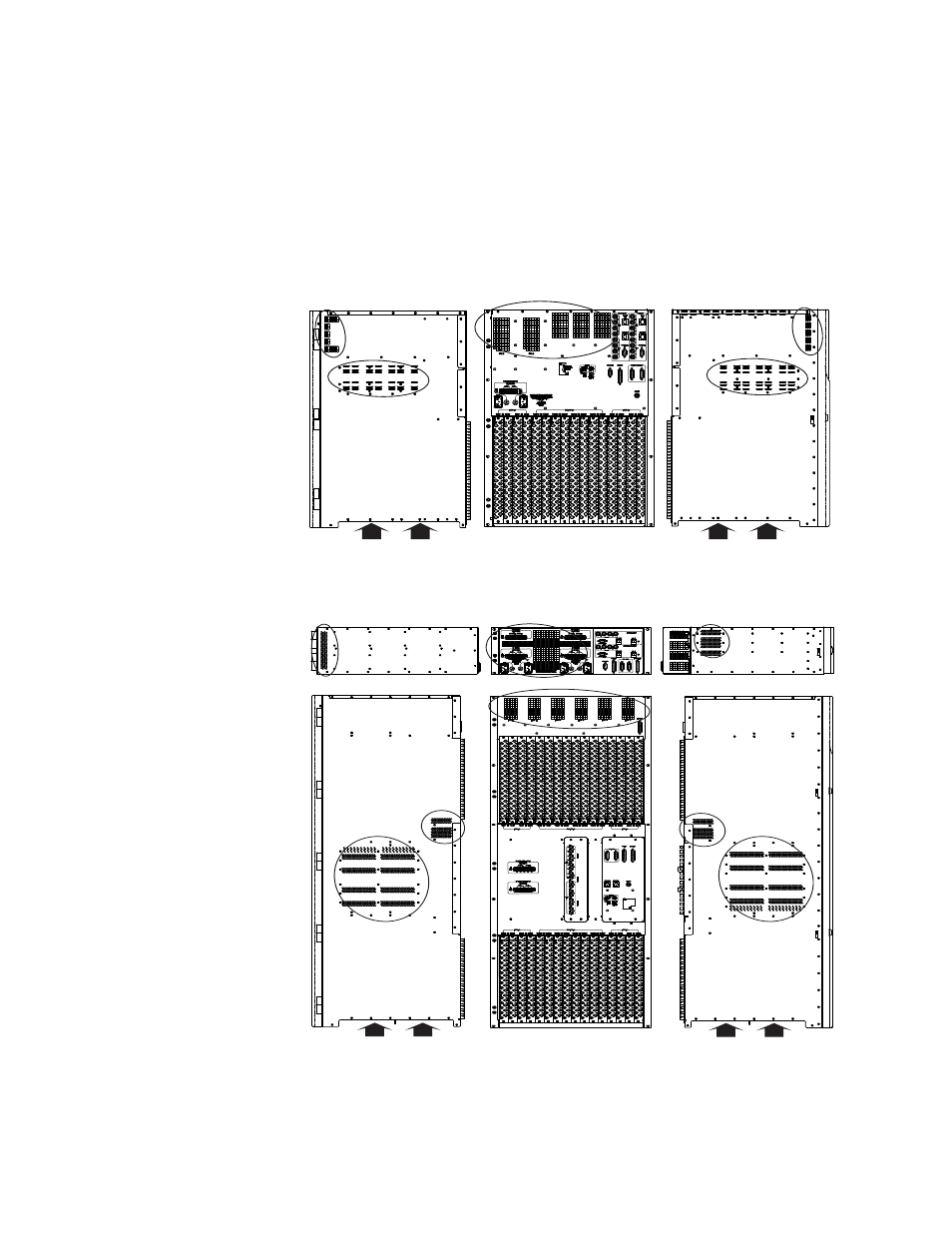
Airflow openings for the 256 and 512 chassis are shown in
and
. Air is taken in from the bottom of the chassis (cut-outs are
located on the very bottom of the sides), and from the central area of the
left and right sides. This air is then drawn up through all of the I/O
cards as well as the matrix boards to the top rear of the chassis and
expelled out the back.
Figure 9. Airflow openings for DV-33256 chassis.
Figure 10. Airflow openings for DV-33512 power supply and main chassis.
Right side
Rear
Left side
IN
IN
IN
OUT
IN
IN
IN
Right side
Rear
Left side
OUT
IN
IN
IN
IN
IN
IN
IN
IN
OUT
Advertising