Settings – Grass Valley XSwitch Feb 08 2006 User Manual
Page 27
XSwitch Installation and Operations Manual
27
Card Setup
When the Card Setup is first displayed, the Rack number flashes. Rack 0
corresponds to the Master Module. Use the Data Up and Data Down
buttons to select the desired module (Rack number). Press SEL to configure
the indicated card rack.
A flashing cursor initially appears over Card 1, configuration mode A.
Press SEL to toggle the operational state of that card. A dark background
behind a letter indicates the card is in switched state in that mode. A light
background behind a letter indicates the card is not in switched state in that
mode. For example (refer to
above):
•
If 1-A has a light colored background, card 1 is unswitched when mode
A is selected.
•
If 1-B has a dark colored background, card 1 is switched when mode B
is selected
Note
Use the Function Up and Function Down buttons to select a new card to con-
figure, use the Data Up and Data Down buttons to select a new mode config-
uration selection for that card.
Settings
When selected from the XSWITCH Menu, Settings information appears on
the LCD display as shown in
below.
Note
Use the Function Up and Function Down buttons to select a setting.
Note
Use the Data Up, Data Down, and SEL buttons to change the selected setting.
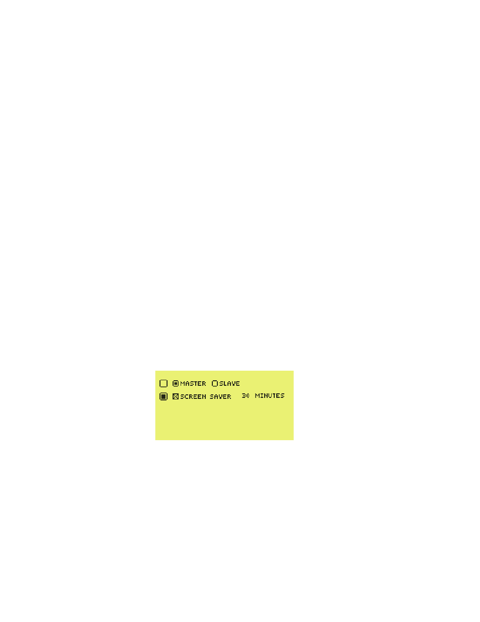
Figure 14. Screen Saver Enable/Disable
Master/Slave
: If Master is selected, the XSWITCH mode will be deter-
mined by the A,B,C,D,E buttons on the front panel. If Slave is selected, the
XSWITCH mode will be determined by another Master device connected
to the serial port on the CPU card. The A,B,C,D,E buttons on the front panel
will NOT change the mode while Slave is selected.
Screen Saver
: Use the SEL button to enable/disable the screen saver. Use
the Data Up and Data Down buttons to determine the length of inactivity
before the screen saver becomes active.