Connector and pinout specifications – Grass Valley XSwitch Feb 08 2006 User Manual
Page 41
XSWITCH Installation and Operation Manual
41
Connector and Pinout Specifications
6.
command string = “1,P,0,0,0”
LEN = 9
input string for CRC = Chr$(4)+Chr$(254)+Chr$(LEN)+com-
mand string
CRC program returns:
complete CRC string = “3AE5”
LSB needed from CRC = “E5”
MSB needed from CRC = “3A”
packet string= = Chr$(4)+Chr$(254)+Chr$(LEN)+command
string+Chr$(&HLSB)+CHR$($&HMSB)
Connector and Pinout Specifications
The connector type is a standard DB9. There is one pin-type (J3) and one
socket-type (J4) connector. The controlling device (PC) would typically
connect to J4.
These are standard, 3 wire RS-232 connections that allow communications
between a controlling device (such as a PC) and the XSWITCH.
They also facilitate communication between multiple XSWITCH units.
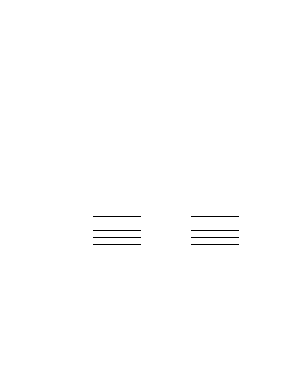
Table 11. J3/J4 Pinouts
J3
J4
PIN #
NAME
PIN #
NAME
1
NC
1
NC
2
TX
2
TX
3
RX
3
RX
4
NC
4
NC
5
GND
5
GND
6
NC
6
NC
7
NC
7
NC
8
NC
8
NC
9
NC
9
NC