See section 17.3.2 – HEIDENHAIN TNC 407 (243 020) Service Manual User Manual
Page 100
SERVICE MANUAL TNC
Issue:
01
Page
82.2
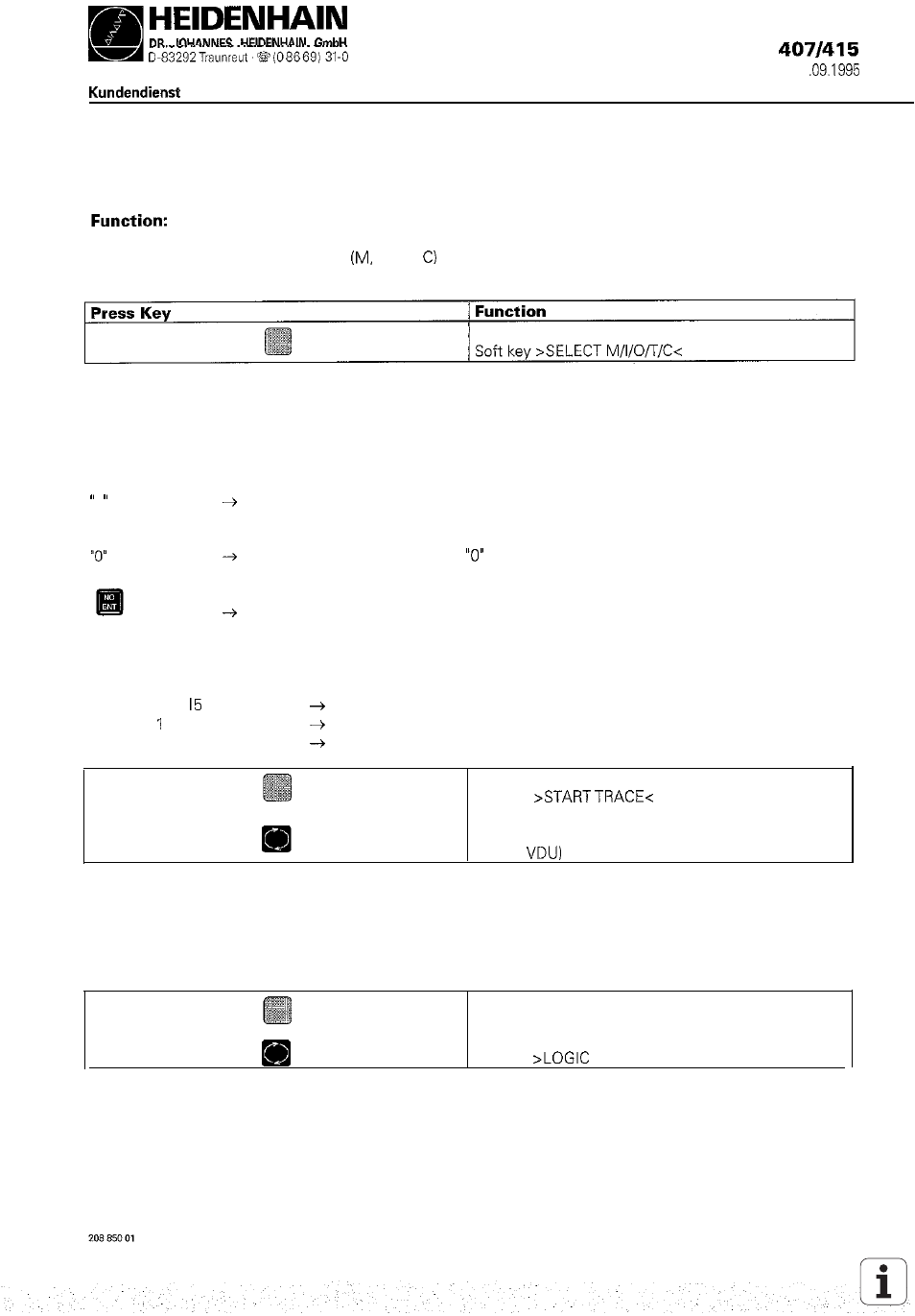
17.3.2 Logic Diagram
The logic states of up to 16 operands
I, 0, T, can be displayed graphically on the screen at the same
time. 1024 PLC scans can be traced.
A table is displayed from which the desired operands can be selected. The control requests the positions of
the table in a dialog. Wrong inputs can be cleared by pressing DEL. It is possible to enter a trigger condition
for each operand. 512 states are traced before and after a trigger event. The following trigger conditions are
possible:
1
e.g.
0
1
trigger on positive edge
0 6
2
trigger on negative edge
2
M7
no trigger
trace if the operand is a logical “1”
(trigger on positive edge)
trace if the operand is a logical
(trigger on negative edge)
no trigger
If no trigger condition is entered for any of the operands,
the operand states are traced continuously and the last
1024 states are stored.
Soft key
Switch TNC to the operating mode MACHINE
(key on
The trace function is started with START TRACE; END TRACE or a trigger event end the tracing
PCTR blinking:
PCTR on:
PCTR off:
trigger condition has not occurred yet
trigger condition has occurred; write access to buffer memory
buffer memory is full. logic diagram can be called.
Switch to TRACE mode
Soft key
DIAGRAM< to call logic diagram