2 f undamentals of p a th f unctions – HEIDENHAIN TNC 320 (340 55x-05) ISO programming User Manual
Page 158
158
Programming: Programming Contours
6.2 F
undamentals of P
a
th F
unctions
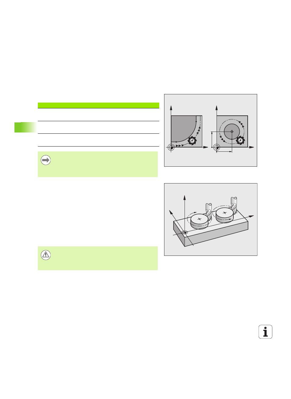
Circles and circular arcs
The TNC moves two axes simultaneously on a circular path relative to
the workpiece. You can define a circular movement by entering the
circle center CC.
When you program a circle, the control assigns it to one of the main
planes. This plane is defined automatically when you set the spindle
axis during a TOOL CALL:
Direction of rotation DR for circular movements
When a circular path has no tangential transition to another contour
element, enter the direction of rotation as follows:
Clockwise direction of rotation: G02/G12
Counterclockwise direction of rotation: G03/G13
Radius compensation
The radius compensation must be in the block in which you move to
the first contour element. You cannot activate radius compensation in
a circle block. Activate it beforehand in a straight-line block (see "Path
Contours—Cartesian Coordinates", page 163).
Pre-positioning
X
Y
X
Y
CC
X
CC
Y
CC
Spindle axis
Main plane
(G17)
XY, also
UV, XV, UY
(G18)
ZX, also
WU, ZU, WX
(G19)
YZ, also
VW, YW, VZ
You can program circles that do not lie parallel to a main
plane by using the function for tilting the working plane
(see User's Manual for Cycles, Cycle 19, WORKING
PLANE) or Q parameters (see "Principle and Overview",
page 202).
G02/G12
G03/G13
X
Z
Y
Danger of collision!
Before running a part program, always pre-position the
tool to prevent the possibility of damaging it or the
workpiece.