1 0 pr ogr amming examples – HEIDENHAIN TNC 426B (280 472) ISO programming User Manual
Page 286
HEIDENHAIN TNC 410, TNC 426, TNC 430
271
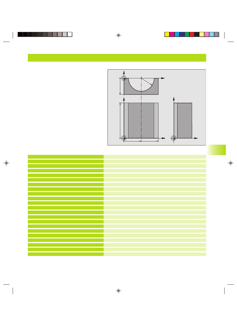
Example: Concave cylinder machined with spherical cutter
Example: Concave cylinder machined with spherical cutter
Center in X axis
Center in Y axis
Center in Z axis
Starting angle in space (Z/X plane)
End angle in space (Z/X plane)
Radius of the cylinder
Length of the cylinder
Rotational position in the X/Y plane
Allowance for cylinder radius
Feed rate for plunging
Feed rate for milling
Number of cuts
Define the workpiece blank
Define the tool
Call the tool
Retract the tool
Call machining operation
Reset allowance
Call machining operation
Retract in the tool axis, end program
%CYLIN G71 *
N10 D00 Q1 P01 +50 *
N20 D00 Q2 P01 +0 *
N30 D00 Q3 P01 +0 *
N40 D00 Q4 P01 +90 *
N50 D00 Q5 P01 +270 *
N60 D00 Q6 P01 +40 *
N70 D00 Q7 P01 +100 *
N80 D00 Q8 P01 +0 *
N90 D00 Q10 P01 +5 *
N100 D00 Q11 P01 +250 *
N110 D00 Q12 P01 +400 *
N120 D00 Q13 P01 +90 *
N130 G30 G17 X+0 Y+0 Z-50 *
N140 G31 G90 X+100 Y+100 Z+0 *
N150 G99 T1 L+0 R+3 *
N160 T1 G17 S4000 *
N170 G00 G40 G90 Z+250 *
N180 L10.0 *
N190 D00 Q10 P01 +0 *
N200 L10.0 *
N210 G00 G40 Z+250 M2 *
Program sequence
■
Program functions only with a spherical cutter.
The tool length refers to the sphere center.
■
The contour of the cylinder is approximated by
many short line segments (defined in Q13). The
more line segments you define, the smoother the
curve becomes.
■
The cylinder is milled in longitudinal cuts (here:
parallel to the Y axis).
■
The machining direction can be altered by
changing the entries for the starting and end
angles in space:
Clockwise machining direction:
starting angle > end angle
Counterclockwise machining direction:
starting angle < end angle
■
The tool radius is compensated automatically.
1
0.1
0 Pr
ogr
amming Examples
X
Y
50
100
100
Z
Y
X
Z
-50
R40
Mkap10.pm6
29.06.2006, 08:06
271