HEIDENHAIN TNC 426 (280 476) User Manual
Page 118
HEIDENHAIN TNC 426, TNC 430
91
4.13 P
allet Oper
ation with T
ool-Or
ient
e
d Mac
h
ining
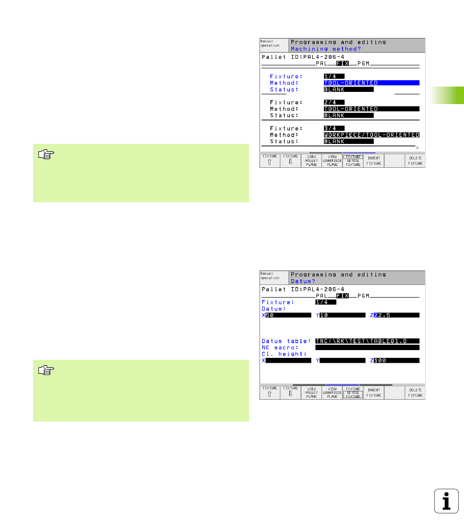
Setting up the fixture plane
n
Fixture:
The number of the fixture is displayed. The number of
fixtures within this plane is shown after the slash.
n
Method
: You can choose between the WORKPIECE ORIENTED and
TOOL ORIENTED machining methods. The selected method is
assumed for the workpiece plane and overwrites any existing
entries. In tabular view, entry WORKPIECE ORIENTED appears as
WPO
, and TOOL ORIENTED appears as TO.
Use the CONNECT/SEPARATE soft key to mark fixtures that are to be
included for calculating the machining process for tool-oriented
machining. Connected fixtures are marked with a dashed line,
whereas separated fixtures are connected with a solid line.
Connected workpieces are marked in tabular view with the entry
CTO
in the METHOD column.
n
Status
: The soft key BLANK identifies the fixture and the
corresponding workpieces as not yet having been machined, and
enters BLANK in the Status field. Use the soft key EMPTY POSITION
if you want to skip the fixture during machining. EMPTY appears in
the Status field.
Setting up details in the fixture plane
n
Fixture:
The number of the fixture is displayed. The number of
fixtures within this plane is shown after the slash.
n
Datum:
Enter the fixture datum
n
Datum table:
Enter the name and path of the datum table valid for
machining the workpiece. The data is carried over to the workpiece
plane.
n
NC macro:
In tool-oriented machining, the macro TCTOOLMODE is
carried out instead of the normal tool-change macro.
n
Safe height:
(optional): Safe position for the individual axes
referenced to the fixture.
The TO-/WP-ORIENTED entry cannot be made via soft
key. It only appears when different machining methods
were chosen for the workpieces in the workpiece plane.
If the machining method was determines in the fixture
plane, the entries are carried over to the workpiece plane,
where they overwrite any existing entries.
Safety positions can be entered for the axes. These
positions can be read with SYSREAD FN18 ID510 NR 6
from NC macros. SYSREAD FN18 ID510 NR 5 can be
used to determine if a value was programmed in the
column. The positions entered are only approached if
these values are read and correspondingly programmed in
the NC macros.