Tool-carrier kinematics, 2 t ool d a ta – HEIDENHAIN iTNC 530 (606 42x-01) User Manual
Page 174
174
Programming: Tools
5.2 T
ool D
a
ta
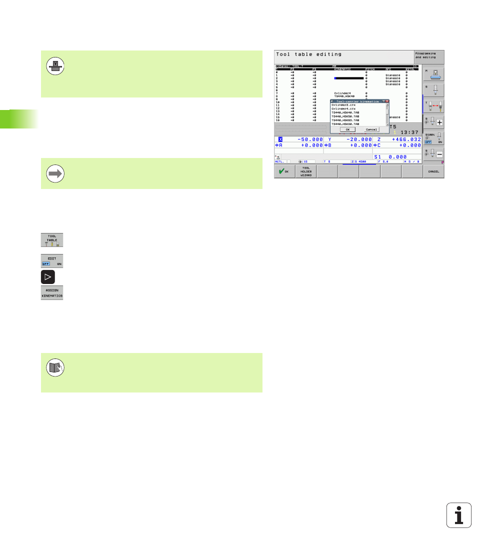
Tool-carrier kinematics
In the KINEMATIC column of the tool table TOOL.T you can assign each
tool with an additional tool carrier kinematic description. In the
simplest case, this carrier kinematics can simulate the taper shank in
order to include it in the dynamic collision monitoring. Also, you can
use this function to very easily integrate angle heads into the machine
kinematic description.
Assigning the tool-carrier kinematics
Follow the procedure below to assign carrier kinematics to a tool:
U
Select any machine operating mode.
U
Press the TOOL TABLE soft key to select the tool
table.
U
Set the EDIT soft key to ON.
U
Select the last soft key row.
U
Show the list of available kinematics: The TNC
displays all carrier kinematics (.TAB files) and all tool-
carrier kinematics you have already parameterized
(.CFX files).
U
Select the desired kinematics configuration with the
arrow keys and confirm your selection with the OK
key.
The TNC must be adapted by your machine tool builder to
be able to account for the tool carrier kinematics. In
particular, your machine tool builder must provide the
corresponding carrier kinematics or parameterizable tool
carriers. Refer to your machine manual.
HEIDENHAIN provides tool-carrier kinematics for
HEIDENHAIN touch probes. If required, please
contact HEIDENHAIN.
Please also note the information on tool-carrier
management in combination with Dynamic Collision
Monitoring (DCM): See “Tool Holder Management (DCM
Software Option)” on page 392.