Setting the datum, 1 f undamentals – HEIDENHAIN iTNC 530 (606 42x-01) User Manual
Page 94
94
Programming: Fundamentals, File Management
3.1 F
undamentals
Setting the datum
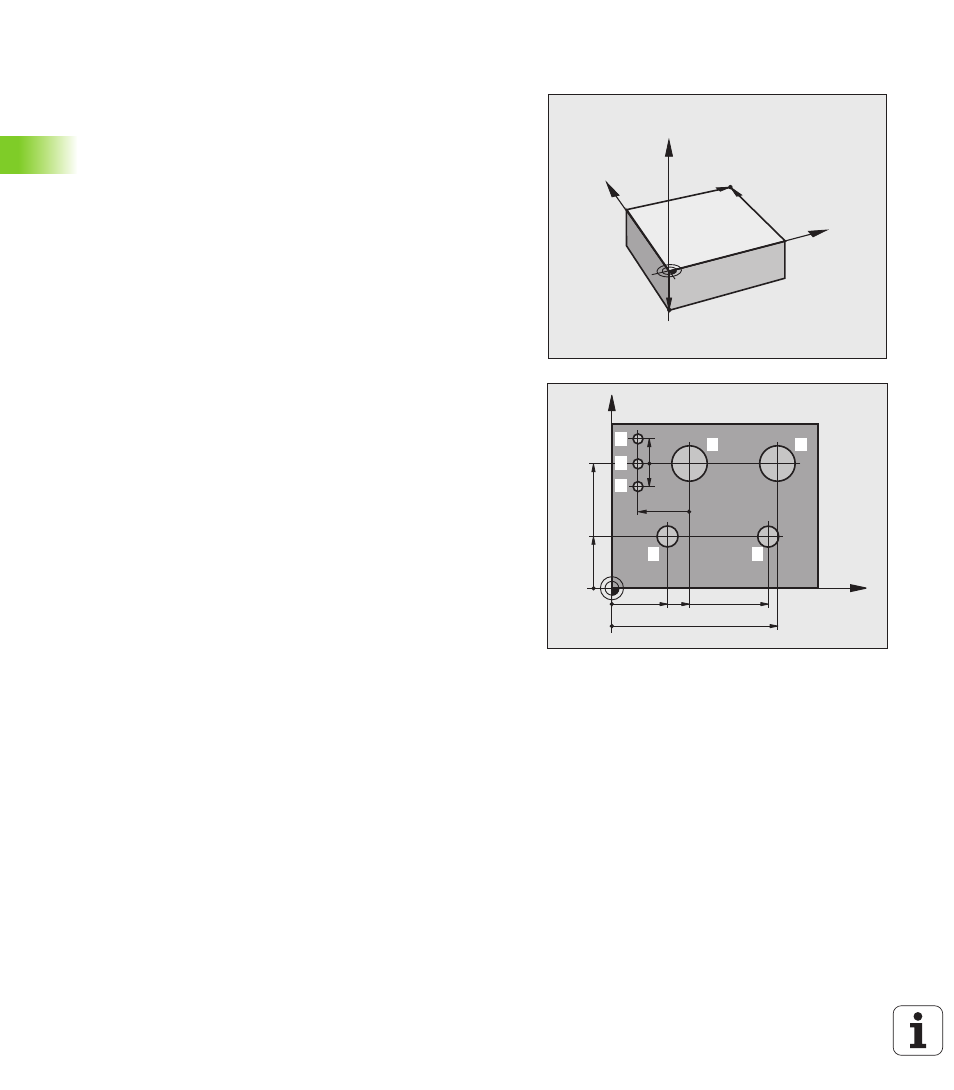
A production drawing identifies a certain form element of the
workpiece, usually a corner, as the absolute datum. Before setting the
datum, you align the workpiece with the machine axes and move the
tool in each axis to a known position relative to the workpiece. Set the
display of the TNC either to zero or to a known position value for each
position. This establishes the reference system for the workpiece,
which will be used for the TNC display and your part program.
If the production drawing is dimensioned in relative coordinates,
simply use the coordinate transformation cycles (see User’s Manual
for Cycle Programming, Cycles for Coordinate Transformation).
If the production drawing is not dimensioned for NC, set the datum at
a position or corner on the workpiece which is suitable for deducing
the dimensions of the remaining workpiece positions.
The fastest, easiest and most accurate way of setting the datum is by
using a 3-D touch probe from HEIDENHAIN. See “Setting the Datum
with a 3-D Touch Probe” in the Touch Probe Cycles User’s Manual.
Example
The workpiece drawing shows holes (
1
to
4
) whose dimensions are
shown with respect to an absolute datum with the coordinates X=0
Y=0. The holes (
5
to
7
) are dimensioned with respect to a relative
datum with the absolute coordinates X=450, Y=750. With the DATUM
SHIFT
cycle you can temporarily set the datum to the position X=450,
Y=750, to be able to program the holes (
5
to
7
) without further
calculations.
Y
X
Z
MAX
MIN
X
Y
325
320
0
450
900
950
150
-150
750
0
30
0±
0,
1
2
1
3
4
7
6
5