2 creating and writing programs, Organization of an nc program in din/iso, Define the blank: g30/g31 – HEIDENHAIN iTNC 530 (606 42x-01) ISO programming User Manual
Page 89
HEIDENHAIN iTNC 530
89
3.2 Cr
eating and W
riting Pr
ogr
a
ms
3.2 Creating and Writing Programs
Organization of an NC program in DIN/ISO
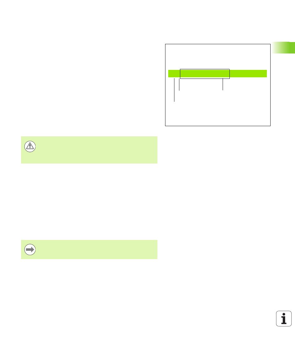
A part program consists of a series of program blocks. The figure at
right illustrates the elements of a block.
The TNC numbers the blocks of a part program automatically
depending on MP7220. MP7220 defines the block number increment.
The first block of a program is identified by %, the program name and
the active unit of measure.
The subsequent blocks contain information on:
The workpiece blank
Tool calls
Approaching a safe position
Feed rates and spindle speeds, as well as
Path contours, cycles and other functions
The last block of a program is identified by N99999999 the program
name and the active unit of measure.
Define the blank: G30/G31
Immediately after initiating a new program, you define a cuboid
workpiece blank. If you wish to define the blank at a later stage, press
the SPEC FCT key and then the BLK FORM soft key. This definition is
needed for the TNC’s graphic simulation feature. The sides of the
workpiece blank lie parallel to the X, Y and Z axes and can be up to 100
000 mm long. The blank form is defined by two of its corner points:
MIN point G30: the smallest X, Y and Z coordinates of the blank
form, entered as absolute values
MAX point G31: the largest X, Y and Z coordinates of the blank form,
entered as absolute or incremental values
N10 G00 G40 X+10 Y+5 F100 M3
Block number
Path function
Words
Block
Danger of collision!
After each tool call, HEIDENHAIN recommends always
traversing to a safe position, from which the TNC can
position the tool for machining without causing a collision!
You only need to define the blank form if you wish to run
a graphic test for the program!