Please note while programming, Cycle parameters – HEIDENHAIN TNC 620 (340 56x-02) Cycle programming User Manual
Page 406
406
Touch Probe Cycles: Automatic Workpiece Inspection
16.13 MEA
S
URE PLANE (Cy
c
le 431, DIN/ISO: G431)
Please note while programming:
Cycle parameters
U
1st meas. point 1st axis Q263 (absolute): Coordinate
of the first touch point in the reference axis of the
working plane. Input range -99999.9999 to
99999.9999
U
1st meas. point 2nd axis Q264 (absolute):
Coordinate of the first touch point in the minor axis of
the working plane. Input range -99999.9999 to
99999.9999
U
1st meas. point 3rd axis Q294 (absolute): Coordinate
of the first touch point in the touch probe axis. Input
range -99999.9999 to 99999.9999
U
2nd meas. point 1st axis Q265 (absolute):
Coordinate of the second touch point in the reference
axis of the working plane. Input range -99999.9999 to
99999.9999
U
2nd meas. point 2nd axis Q266 (absolute):
Coordinate of the second touch point in the minor axis
of the working plane. Input range -99999.9999 to
99999.9999
U
2nd meas. point 3rd axis Q295 (absolute):
Coordinate of the second touch point in the touch
probe axis. Input range -99999.9999 to 99999.9999
U
3rd meas. point 1st axis Q296 (absolute): Coordinate
of the third touch point in the reference axis of the
working plane. Input range -99999.9999 to
99999.9999
U
3rd meas. point 2nd axis Q297 (absolute):
Coordinate of the third touch point in the minor axis of
the working plane. Input range -99999.9999 to
99999.9999
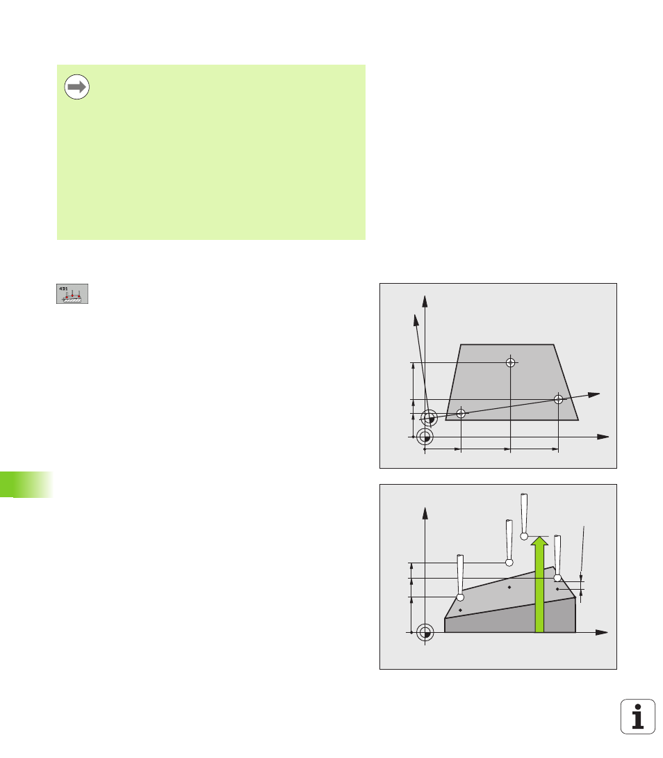
Before a cycle definition you must have programmed a
tool call to define the touch probe axis.
For the TNC to be able to calculate the angular values, the
three measuring points must not be positioned on one
straight line.
The spatial angles that are needed for tilting the working
plane are saved in parameters Q170 – Q172. With the first
two measuring points you also specify the direction of the
reference axis when tilting the working plane.
The third measuring point determines the direction of the
tool axis. Define the third measuring point in the direction
of the positive Y axis to ensure that the position of the tool
axis in a clockwise coordinate system is correct.
X
Y
Q297
Q263
Q264
Q266
Q296
Q265
Y'
X'
X
Z
Q295
Q298
Q294
Q260
SET_UP
(TCHPROBE.TP)
+
Q320