Yaskawa YASNAC PC NC PLC Programming Manual User Manual
Page 38
6 - 2
YASNAC PCNC PLC Programming Manual Chapter 6: PLC Instructions
6.1 Registers
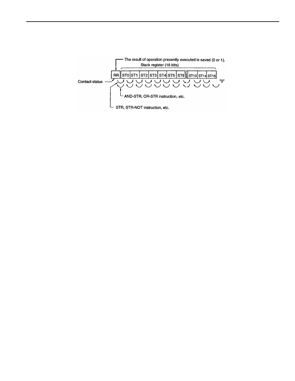
The PLC has registers where the intermediate results of logical operation in a sequence program
are saved. Configuration of these registers is “1bit +16bits”.
6.1.1
Result Register (RR)
This is a one-bit register where the result of presently executed operation is set.
Setting the status (0 or 1) of contact to RR by using the LD instruction and outputting the contents
of RR to the relay address by using the OUT instruction are possible.
It is also possible to shift the contents of RR to the stack register by one bit or to shift the contents
of the stack register to RR by one bit after the completion of operation by using the STR or AND-
STR instruction.
6.1.2 Stack Register (ST0 to ST15)
When executing a long logical operation, it is possible to save the intermediate result to the stack
register by up to 16 bits.
The STR and STR-NOT instructions move the data in RR to ST0 and, sequentially, the data in the
stack registers to the right one bit.
The AND-STR and OR-STR instructions execute the operation between the data in ST0 and RR,
set the result to RR and shift the data in stack register to the left by one bit. After the execution of
these instructions, “0” is set for ST15. Both the number of STR and STR-NOT instructions, and
the number of AND-STR and OR-STR instructions must be the same during the execution of a
series of logical operations, otherwise, an error occurs. In other words, the number of data saving
times to the stack register and the number of data fetching times from the stack register must be
the same.