7 option card installation, Prior to installing the option, 7option card installation – Yaskawa L1000E AC Drive CIMR-LEA User Manual
Page 148: Yea_comm
148
YASKAWA TOEPYAIL1E01A YASKAWA AC Drive L1000E Quick Start Guide
7 Option Card Installation
7
Option Card Installation
This section provides instructions on installing the option cards listed in
.
◆ Prior to Installing the Option
Prior to installing the option, wire the drive, make the necessary connections to the drive terminals, and verify that the
drive functions normally. Refer to the
for information on wiring and connecting the drive.
below lists the number of option cards that can be connected to the drive and the drive connectors for connecting
those option cards.
Table 42 Option Card Installation
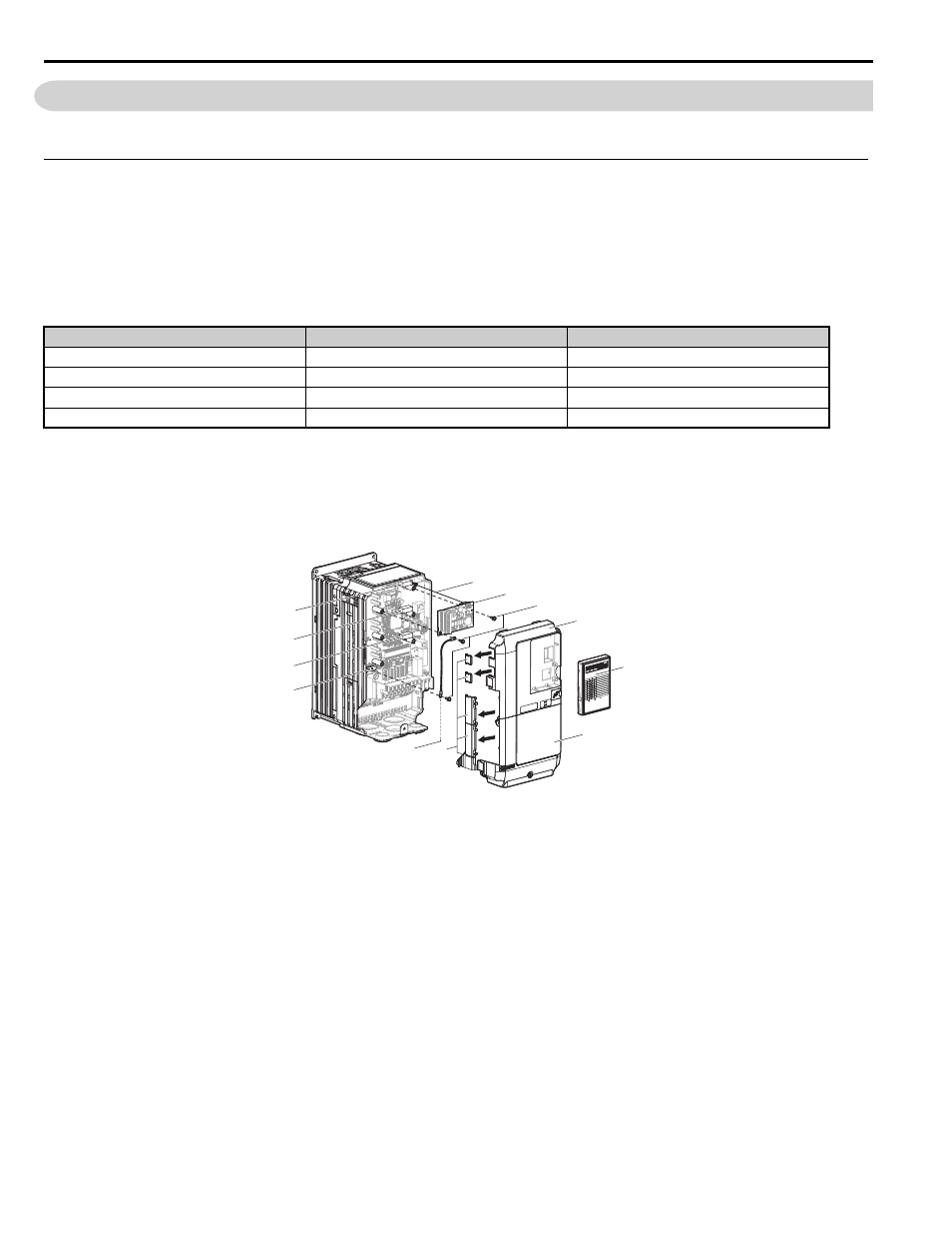
shows an exploded view of the drive with the option and related components for reference.
Figure 80
Figure 87 Installing an Option Card
Option Card
<1> If two PG option cards are connected, use both CN5-B and CN5-C. If only one PG option card is connected to the drive, use the CN5-C
connector.
<2> When DI-A3 is to be used as monitors, the card can be connected to any of CN5-A, B or C. The input status of DI-A3 can then be
viewed using U1-17.
Connector
Number of Cards Possible
PG-B3, PG-X3
CN5-C
DO-A3, AO-A3
CN5-A, B, C
1
PG-F3, PG-E3
CN5-C
1
CN5-A
1
A – Insertion point for CN5
G – Removable tabs for wire routing
B – Option card
H – Ground wire
C – Included screws
I – Drive grounding terminal (FE)
D – Front cover
J – Connector CN5-A
E – Digital operator
K – Connector CN5-B
F – Terminal cover
L – Connector CN5-C
G
A
B
C
H
D
E
F
I
J
K
L
PWR
LED MON
ITOR
JVOP-
184
RUN
DS1
DS2
RUN
DS1
DS2
STATU
S
READY
RUN
ALARM(
RUN)
PGOH,
LT
BB,HB
B
EF,SE
Other
Fault
OV,UV
OH,OL
OC,GF,
SC,PGO
CPF,OF
A,OFB,
OFC
:LIGH
T
:BLIN
K
:LIGH
T OFF
YEA_comm