U: monitors on, Rated current, U: monitors – Yaskawa L1000E AC Drive CIMR-LEA User Manual
Page 208: B parameter table

B Parameter Table
208
YASKAWA TOEPYAIL1E01A YASKAWA AC Drive L1000E Quick Start Guide
■
U: Monitors
Monitor parameters allow the user to view drive status, fault information, and other data concerning drive operation.
U1: Operation Status Monitors
T2-19
(BB1H)
Rotation Direction for Auto-
Tuning of PG-E3 Encoder
Characteristics
Sets the direction of motor rotation for execution of Auto-Tuning of PG-E3
encoder characteristics (T2-01 = 12).
0: Forward (Up)
1: Reverse (Down)
Default: 0
Min: 0
Max: 1
<1> Default setting value varies by the drive model (o2-04).
<2> Values shown here are for 200 V class drives. Double the value when using a 400 V class drive.
<3> The display resolution depends on the rated output power of the drive. Models 2A0018 to 2A0041 and 4A0009 to 4A0023 display values in 0.01
A units, while models 2A0059 to 2A0432 and 4A0030 to 4A0260 display values in 0.1 A units.
<4> Setting units are determined by the induced voltage constant unit selection for PM motors set to T2-13.
<5> Maximum value is 48 when a PG-E3 option is connected.
<6> Setting 12 requires a PG-E3 option with software version 1102 or later. To identify the PG-E3 software version, refer to the PG-E3 label on the
option in the field designated “C/N” (S + four-digit number).
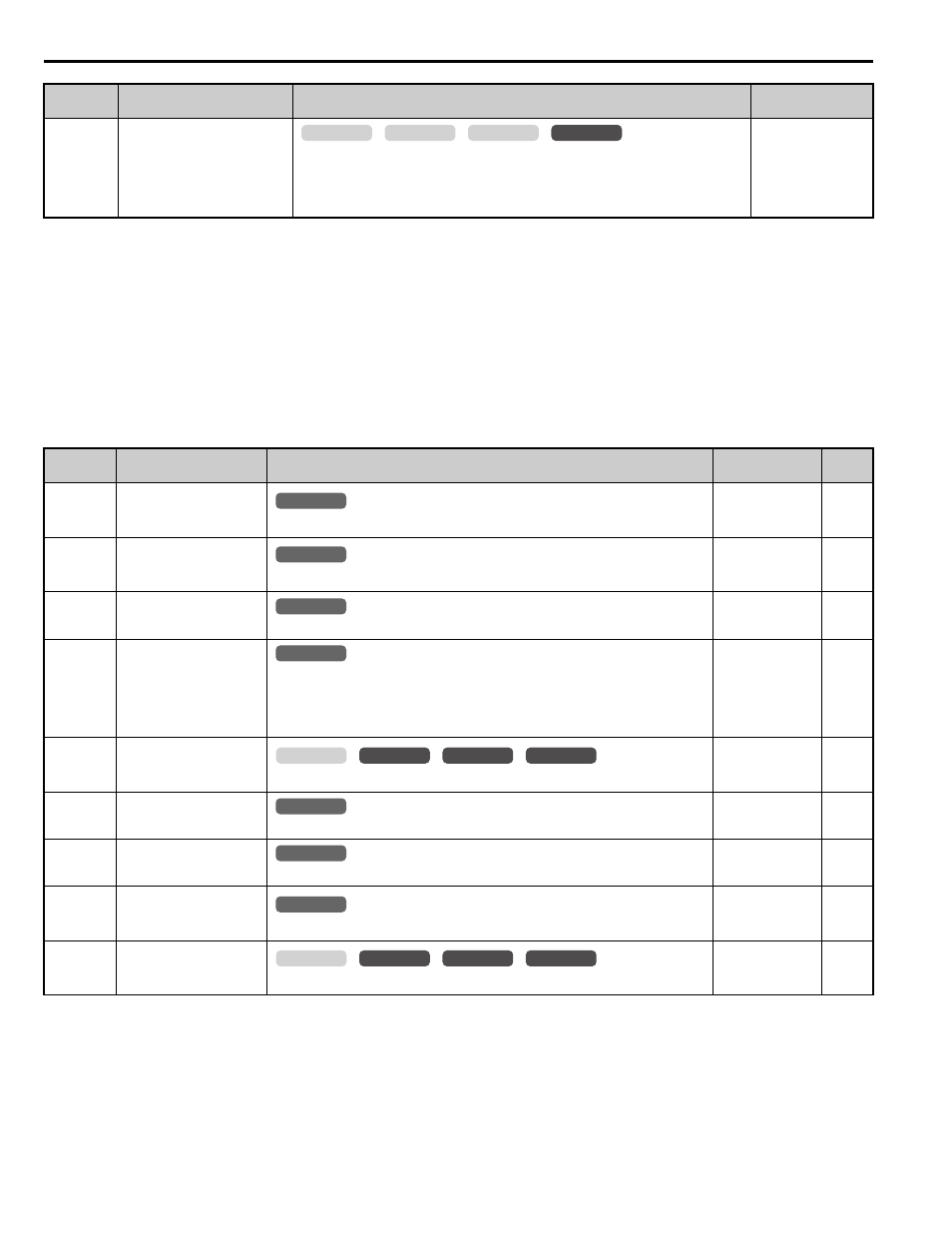
No.
(Addr.)
Name
Description
Analog Output
Level
Unit
U1-01
(40H)
Speed Reference
Monitors the speed reference.
10 V: Max
frequency
(-10 to +10 V)
0.01%
U1-02
(41H)
Output Speed
Displays the output speed.
10 V: Max
frequency
(-10 to +10 V)
0.01%
U1-03
(42H)
Output Current
Displays the output current.
10 V: Drive rated
current
U1-04
(43H)
Control Method
0: V/f Control
2: Open Loop Vector Control
3: Closed Loop Vector Control
7: Closed Loop Vector Control for PM
No signal output
available
–
U1-05
(44H)
Speed Feedback
Displays the motor speed feedback.
10 V: Max
Frequency
(-10 to +10 V)
0.01%
U1-06
(45H)
Output Voltage
Reference
Displays the output voltage.
10 V: 200
Vrms
0.1 Vac
U1-07
(46H)
DC Bus Voltage
Displays the DC bus voltage.
10 V: 400 V
1 Vdc
U1-08
(47H)
Output Power
Displays the output power (this value is calculated internally).
10 V: Drive rated
power (kW)
(-10 to +10 V)
U1-09
(48H)
Torque Reference
Monitors the internal torque reference.
10 V: Motor rated
torque
(-10 to +10 V)
0.1%
No.
(Addr.)
Name
Description
Setting
common
_
CLV
CLV/PM
V/f
OLV
All Modes
common
_
All Modes
common
_
All Modes
common
_
All Modes
common
_
common
_
CLV
CLV/PM
V/f
OLV
All Modes
common
_
All Modes
common
_
All Modes
common
_
common
_
CLV
CLV/PM
V/f
OLV