Yaskawa Portable Control Display Unit User Manual
Page 42
6
TEST MENU
36
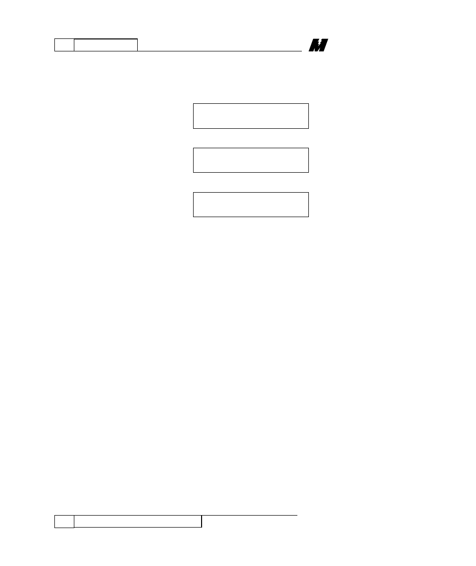
The Trace Monitor Function
01/22/96
will be similar to one of the formats below,
assuming that the data is available:
(Floating Point)
(Fixed Point)
OR
(LOGIC)
OR
The top line is divided into three parts.
The five-digit number following “Blk” is
the block number currently in this Trace
Buffer. The word “In” or “Out” indicates
whether an input or an output is being
traced. The two-digit number at the far
right is the I/O number of the block. The
bottom line is divided into three parts. The
single digit following the “#” indicates
which of the four Trace Buffers is currently
in the display. This number will always be
between 0 and 3 inclusive. Following the
trace buffer number is either an “R”, an
“F”, or the word “LOGIC”. This indicates
what type of data is currently being
viewed. The “R” means “REAL” (floating
point) data, the “F” means “FIXED” (non-
floating point) data, and the “LOGIC”
means the I/O being shown is a logic
signal. Note that a “FIXED POINT”
number may have digits to the right of the
decimal point, while an integer will not.
Blk 00112 Out 00
#0 LOGIC OFF
Blk 00243 Out 03
#0 R 9.73323E-04
Blk 00243 Out 03
#0 R 9.73323E-04