Versatec ™ interface setup – iSys V24 Direct Thermal Printer User Manual
Page 8
8
Versatec
™ Interface Setup
CAUTION: The electronic components of the V24 plotter can be damaged by
electrostatic discharge (ESD). To avoid ESD, maintain contact with a ground source. A
grounded wrist strap or similar should be used.
WARNING: Electric shock warning.
1. Pull on lid latches and lift lid slightly (see figure 12).
2.
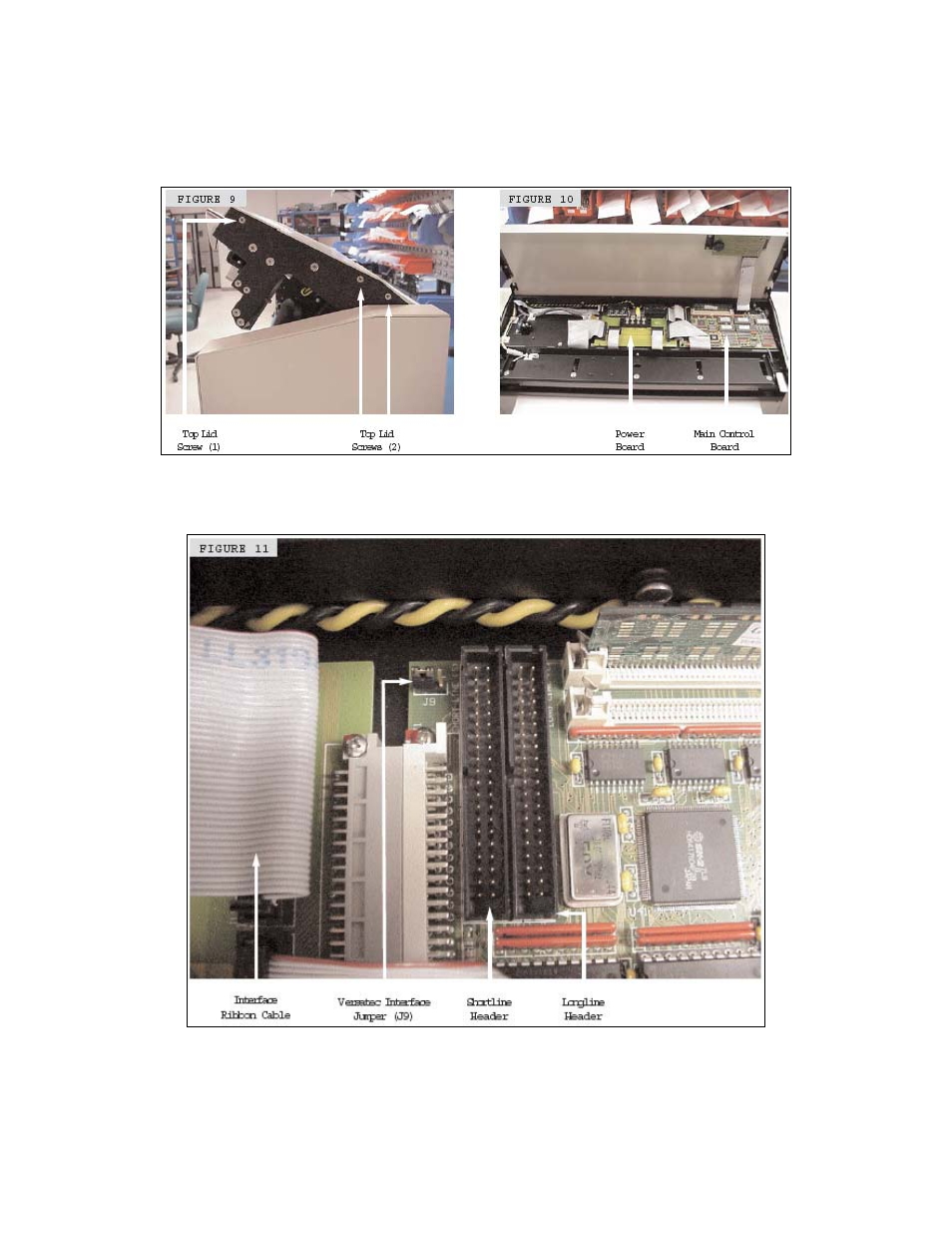
Remove 3 screws on each of the left and right side arms of the lid (see figure 9).
3. Lift up on the lid cover to expose the main control board electronics (see figure 10.)
1. Unplug interface ribbon cable.
2. Move interface jumper J9 to select “S”(shortline) or “L”(longline).
3. Plug interface ribbon cable into the header to match the interface jumper J9
setting.
NOTE: Figure above shows the interface jumper J9, set to shortline.